
Frequency monitoring to detect plasma process abnormality

a plasma process and frequency monitoring technology, applied in the field of frequency monitoring to detect plasma process abnormalities, can solve the problem of causing more serious damage to chamber components or workpieces

Inactive Publication Date: 2011-03-08
APPLIED MATERIALS INC
View PDF23 Cites 22 Cited by
  • Summary
  • Abstract
  • Description
  • Claims
  • Application Information

AI Technical Summary

Benefits of technology

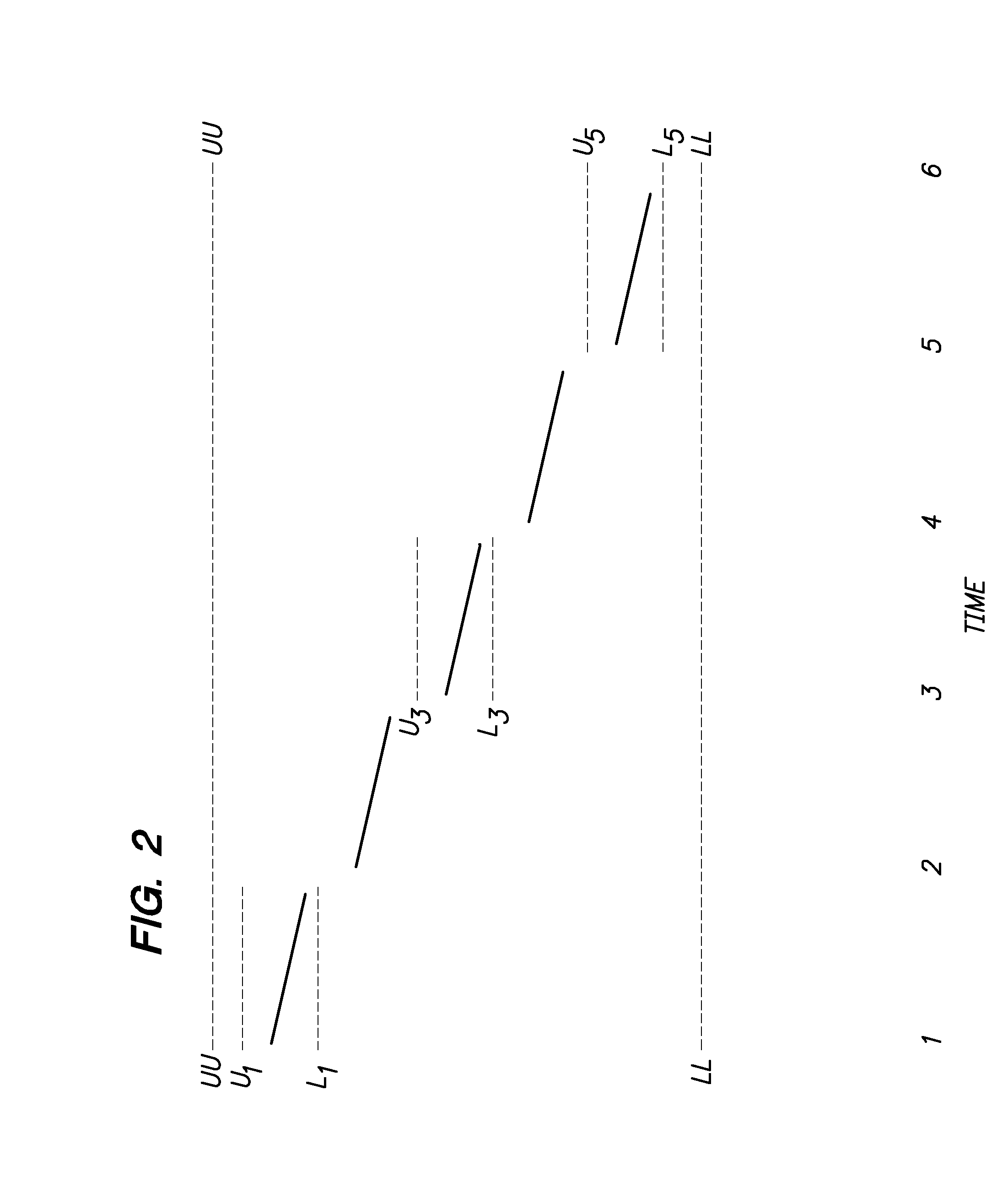
The invention is an apparatus and method for detecting abnormal conditions in an RF-powered plasma process chamber. It does this by monitoring the frequency of the RF power supply to ensure it remains within established limits. The invention can adaptively establish new frequency limits when a new process step begins or after a change in the state of the process chamber. The first aspect of the invention uses a sample-and-hold circuit to sample the frequency of the RF power supply and establish the first pair of lower and upper frequency limits. The second aspect of the invention uses a comparator circuit to compare the frequency of the RF power supply with the second pair of frequency limits and signal an alert if the power supply frequency is outside the limits. The invention can detect abnormal conditions in the process chamber, such as damaged chamber components or damaged workpiece, and can adapt the frequency limits to drifts in the process chamber conditions. The invention has complementary and synergistic advantages and shortcomings, and can be used together with other methods for detecting abnormal conditions in the process chamber.

Problems solved by technology

Such malfunctions can include a damaged chamber component, a chamber component that requires cleaning or other routine maintenance, or a damaged workpiece.
If a plasma process is not halted after a malfunction occurs, there is a risk of producing more serious damage to the chamber components or the workpiece.

Method used


Image

  • Frequency monitoring to detect plasma process abnormality
  • Frequency monitoring to detect plasma process abnormality
  • Frequency monitoring to detect plasma process abnormality

Examples


Embodiment Construction

1. Overview of Plasma Process

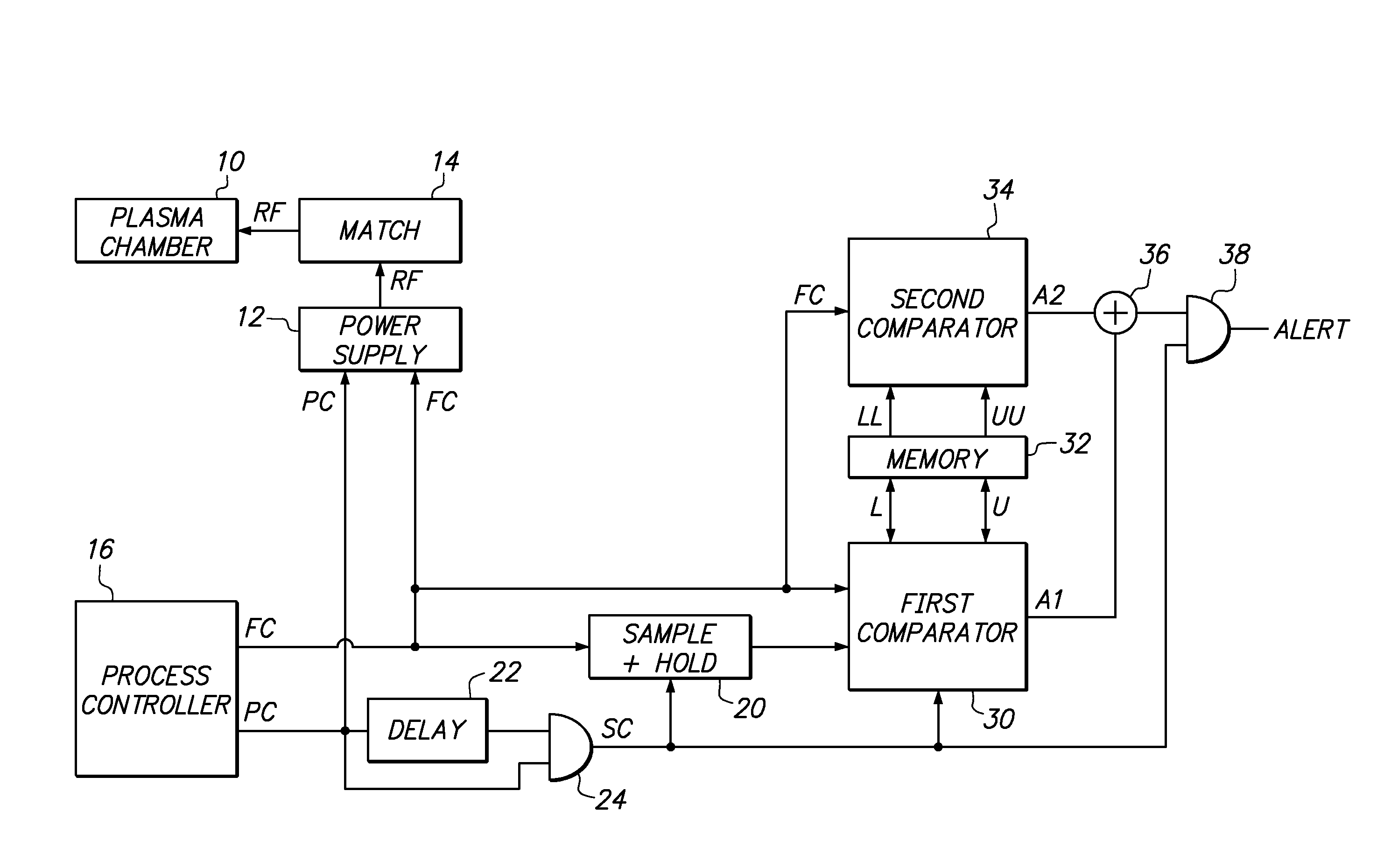
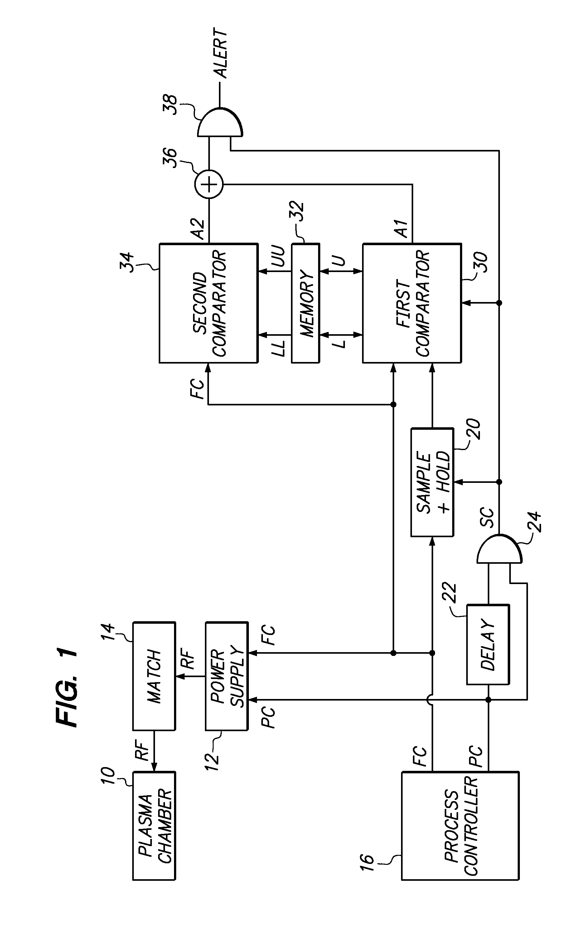
[0019]FIG. 1 shows a conventional RF-powered plasma process chamber 10 and a novel electrical circuit 20-24 according to the present invention for detecting abnormal conditions within the process chamber.

[0020]The plasma process chamber can be any type of chamber for performing a plasma process useful for manufacturing electronic devices such as electronic displays or semiconductor integrated circuits. For example, the plasma process chamber can be a plasma-enhanced chemical vapor deposition chamber, a sputtering chamber, or a plasma etch chamber.

[0021]The illustrated plasma process chamber 10 includes an RF coupling electrode, not shown, that is connected to receive RF power from the output of a conventional RF power supply 12. The RF coupling electrode functions to couple RF power to a plasma within the chamber. For example, the RF electrode may be a capacitively coupled electrode, an induction coil, or a microwave waveguide. The process chamber also m...


PUM


Abstract

Abnormal conditions within an RF-powered plasma process chamber are detected by detecting whether the frequency of a variable-frequency RF power supply moves outside established lower and upper limits. In a first aspect, a first pair of lower and upper limits are established as a function of the frequency of the power supply sampled after a new process step begins or after a sample control signal changes state. In a second aspect, a second pair of lower and upper limits are not adapted to the frequency of the power supply. Both aspects preferably are used together to detect different occurrences of abnormal conditions.

Description

CROSS REFERENCE TO RELATED APPLICATION[0001]This application claims the benefit of U.S. Provisional application No. 60 / 826,539 filed Sep. 21, 2006.FIELD OF THE INVENTION[0002]The invention relates to apparatus and methods for detecting abnormal conditions within an RF-powered plasma process chamber that is coupled to a variable-frequency RF power supply, especially a process chamber for fabricating an electronic workpiece such as an electronic display or semiconductor circuit.BACKGROUND OF THE INVENTION[0003]Electronic devices such as electronic flat panel displays and semiconductor integrated circuits generally are manufactured by performing a sequence of process steps in various process chambers. Such process steps commonly include steps performed within plasma process chambers, such as a deposition step performed in a plasma-enhanced chemical vapor deposition chamber or a plasma sputtering chamber, or an etch step performed in a plasma etch chamber. Any chamber for performing a s...

Claims


Application Information

Patent Timeline
Patent Type & Authority Patents(United States)
IPC IPC(8): G08B21/00
CPCH01J37/32174H01J37/32935H03H7/40G01R23/005G01R23/15H01L21/67213G08B21/182
Inventor PARK, BEOM SOOCHOI, SOO YOUNGWHITE, JOHN M.KIM, HONG SOONHOFFMAN, JAMES
Owner APPLIED MATERIALS INC
Learn More