
UWB radio interface with DC offset

a radio interface and offset technology, applied in the field of wireless communication, can solve the problems of radio rendering non-functional, large undesirable direct current offset, and common problems of digital communication receivers employing direct conversion radios

Inactive Publication Date: 2011-03-08
WIQUEST COMMUNICATIONS +1
View PDF10 Cites 0 Cited by
  • Summary
  • Abstract
  • Description
  • Claims
  • Application Information

AI Technical Summary

Benefits of technology

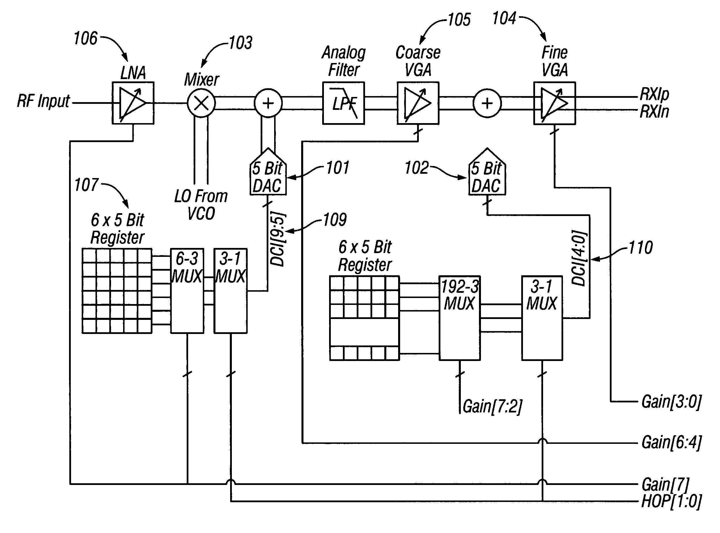
The present invention provides a way to correct direct current (DC) offsets in radio signals. It involves a radio processor and a baseband processor. The baseband processor measures the DC offset produced by the radio processor and generates a correction value. This value is then stored in a memory in the radio processor. The radio processor then uses this correction value to produce an analog signal that can be sent to a radio receive path to cancel out the unwanted DC offset. This invention allows for improved quality of radio signals.

Problems solved by technology

Digital communication receivers that employ a direct conversion radio all suffer from a common problem.
Due to the high amount of gain at baseband, these radios can often create large undesirable direct current (DC) offset in the output signal.
If there is no correction for this offset, the radio is rendered non-functional.
The interface can be either analog or digital, but both options have drawbacks.
The drawback of the analog interface is that it requires adding a digital to analog converter (DAC) to the baseband chip which is primarily a digital chip.
This adds to the cost of the baseband processor.
However, a digital interface may require many pins to represent the DC correction values with enough resolution, adding cost to both the radio and baseband processor.

Method used


Image

  • UWB radio interface with DC offset
  • UWB radio interface with DC offset
  • UWB radio interface with DC offset

Examples


Embodiment Construction

[0014]The present invention provides a method and apparatus for eliminating the need for a high speed digital or analog interface dedicated to communicating DC offset correction values. The invention uses a “thin” interface, in that it requires very few interface pins. The elimination of the dedicated interface reduces the cost of both the radio and the baseband processor chips.

[0015]The invention uses a serial processor interface which may be incorporated into both the baseband and radio chips exclusively to convey the DC offset correction values. Typically, both chips already have such a serial processor interface to communicate other control information, which can also be used to convey the offset values.

[0016]The invention includes digital interfaces between the radio and baseband processor for any interface that can effect a change in the radio which would require a change to the current DC correction value used. Typically, a unique DC offset correction value is required for ea...


PUM


Abstract

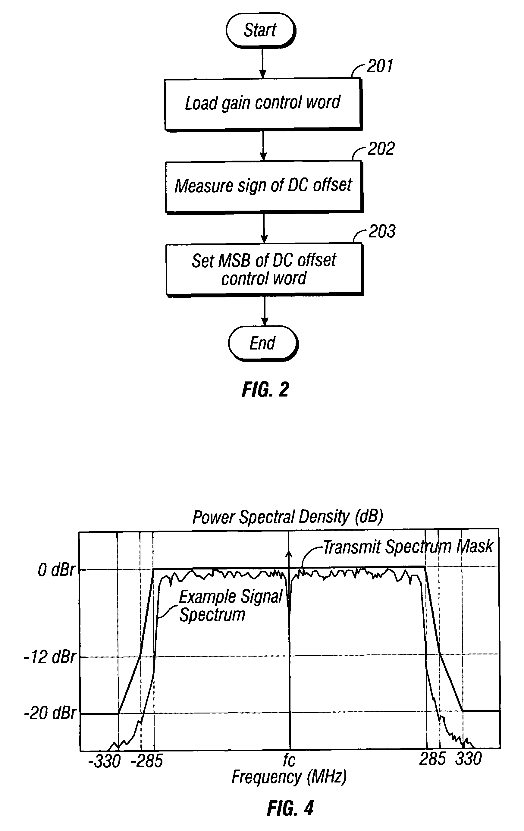
The present invention provides a method and apparatus for correcting direct current (DC) offsets in radio output signals. The invention comprises a radio processor and a baseband processor. During a calibration routine, the baseband processor measures DC offset produced by the radio processor, generates a corresponding DC offset correction value, and writes the correction value to a discrete memory in the radio processor via a serial processor interface. During a subsequent normal receive operation, the radio processor reads the DC offset correction value from memory and feeds it into a into a digital to analog converter to produce an analog signal that in turn is fed into a radio receive path to nullify undesired DC offset.

Description

TECHNICAL FIELD[0001]The invention relates generally to wireless communication, and more specifically to the correction of DC offsets in radio output signals.BACKGROUND OF THE INVENTION[0002]Digital communication receivers that employ a direct conversion radio all suffer from a common problem. Due to the high amount of gain at baseband, these radios can often create large undesirable direct current (DC) offset in the output signal. DC offset is a DC bias voltage that is added to the input of a circuit or amplifier. If there is no correction for this offset, the radio is rendered non-functional.[0003]A few schemes exist for correcting these DC offsets in the radio, which usually include injecting a DC current of the opposite sign into the radio to nullify the DC offset. Previously, the source of this correction current was from a second device external to the radio; typically, a baseband processor chip.[0004]This mechanism requires a very high speed interface between the two devices ...

Claims


Application Information

Patent Timeline
Patent Type & Authority Patents(United States)
IPC IPC(8): H04L25/06H04W4/00H04B1/10
CPCH04B1/30
Inventor JOSEPH, BRIAN C.
Owner WIQUEST COMMUNICATIONS
Learn More