
Radio frequency filtering technique with auto calibrated stop-band rejection

a radio frequency filtering and stop-band rejection technology, applied in the field of communication systems, can solve the problems of inability to integrate a saw filter, increased cost due to an increase in a number of components, and less flexibility in sharing lna b>206/b> in multi-band applications, and particularly in software-defined radios

Inactive Publication Date: 2011-03-08
AVAGO TECH INT SALES PTE LTD
View PDF14 Cites 14 Cited by
  • Summary
  • Abstract
  • Description
  • Claims
  • Application Information

AI Technical Summary

Benefits of technology

The patent describes methods, systems, and apparatuses for filtering received radio frequency signals. The invention provides a way to filter out unwanted signals while keeping the desired information signal. The filtering is done by down-converting the signal and then filtering it in two different signal paths. The two signals are then combined to create a new signal that does not include the unwanted signals. The invention also allows for the adjustment of signal phase to match the signal paths. The technical effects of the invention include improved signal quality, reduced interference, and improved signal processing.

Problems solved by technology

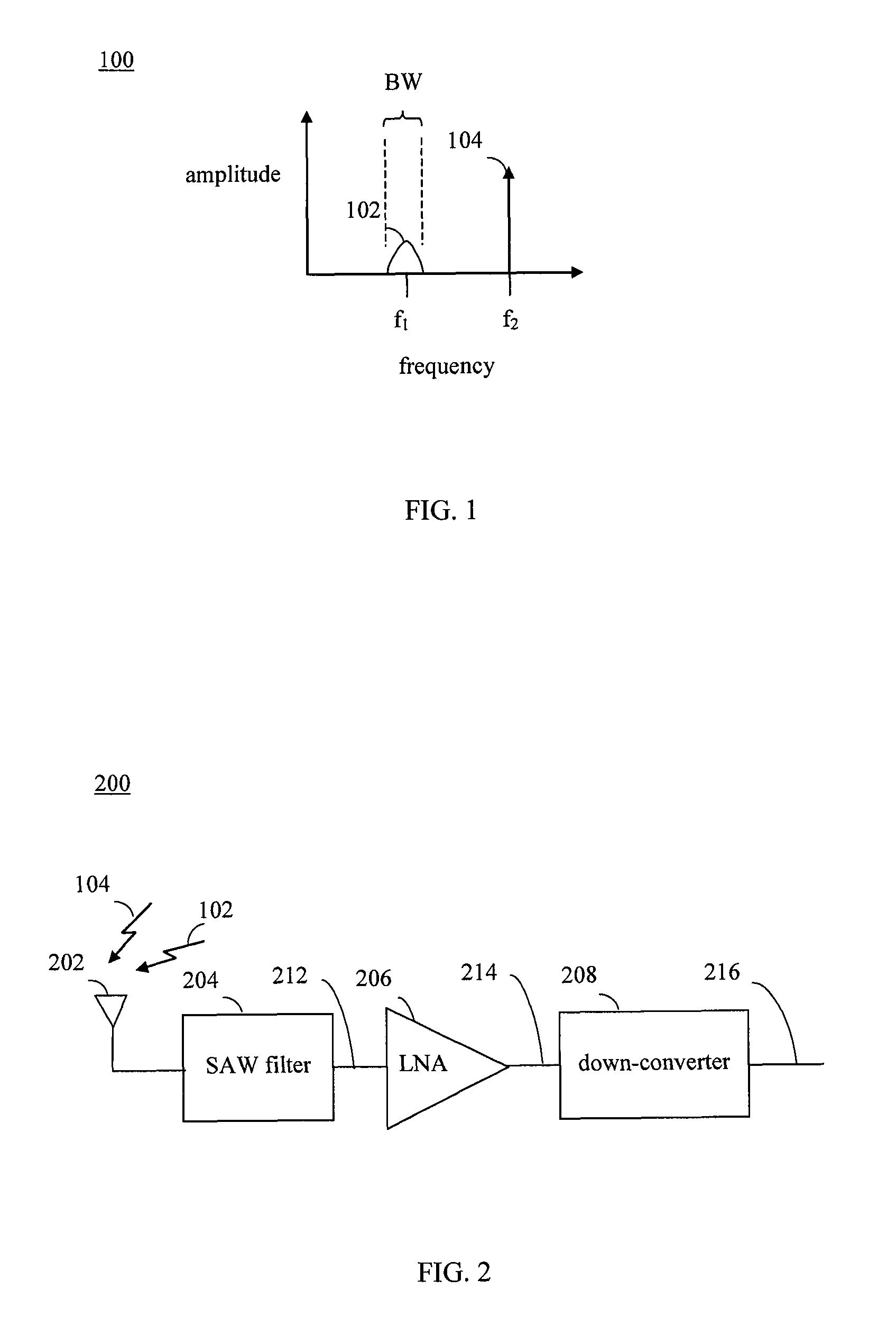
Due to the modest Q of on-chip inductors, it is not practical to integrate a SAW filter 204 having such filter sharpness in the same integrated circuit chip as LNA 206 and / or the rest of receiver 200.
First, cost is increased due to an increase in a number of components, especially in multi-mode, multi-band applications.
Third, there is less flexibility in sharing LNA 206 in multi-band applications, and particularly in software-defined radios.

Method used


Image

  • Radio frequency filtering technique with auto calibrated stop-band rejection
  • Radio frequency filtering technique with auto calibrated stop-band rejection
  • Radio frequency filtering technique with auto calibrated stop-band rejection

Examples


example embodiments

[0040]In embodiments, improved ways of filtering RF signals is provided. For example, embodiments may be implemented in receivers, transmitters, transceivers, and / or other portions of a communications system. Embodiments of the present invention can be incorporated into any type of communication system, including cellular networks, wireless local area networks (WLANs), wirelessly broadcast digital television systems, wirelessly broadcast digital radio systems, and other types of communication systems. For instance, embodiments can be implemented in stationary communication devices and handheld communication devices, such as mobile phones (e.g., cell phones), handheld computing devices (e.g., personal digital assistants (PDAs), Blackberry™ devices, Palm Pilots™, etc.), laptop computers, portable music players, mobile television devices, etc.

[0041]The example embodiments described herein are provided for illustrative purposes, and are not limiting. The examples described herein may be...


PUM


Abstract

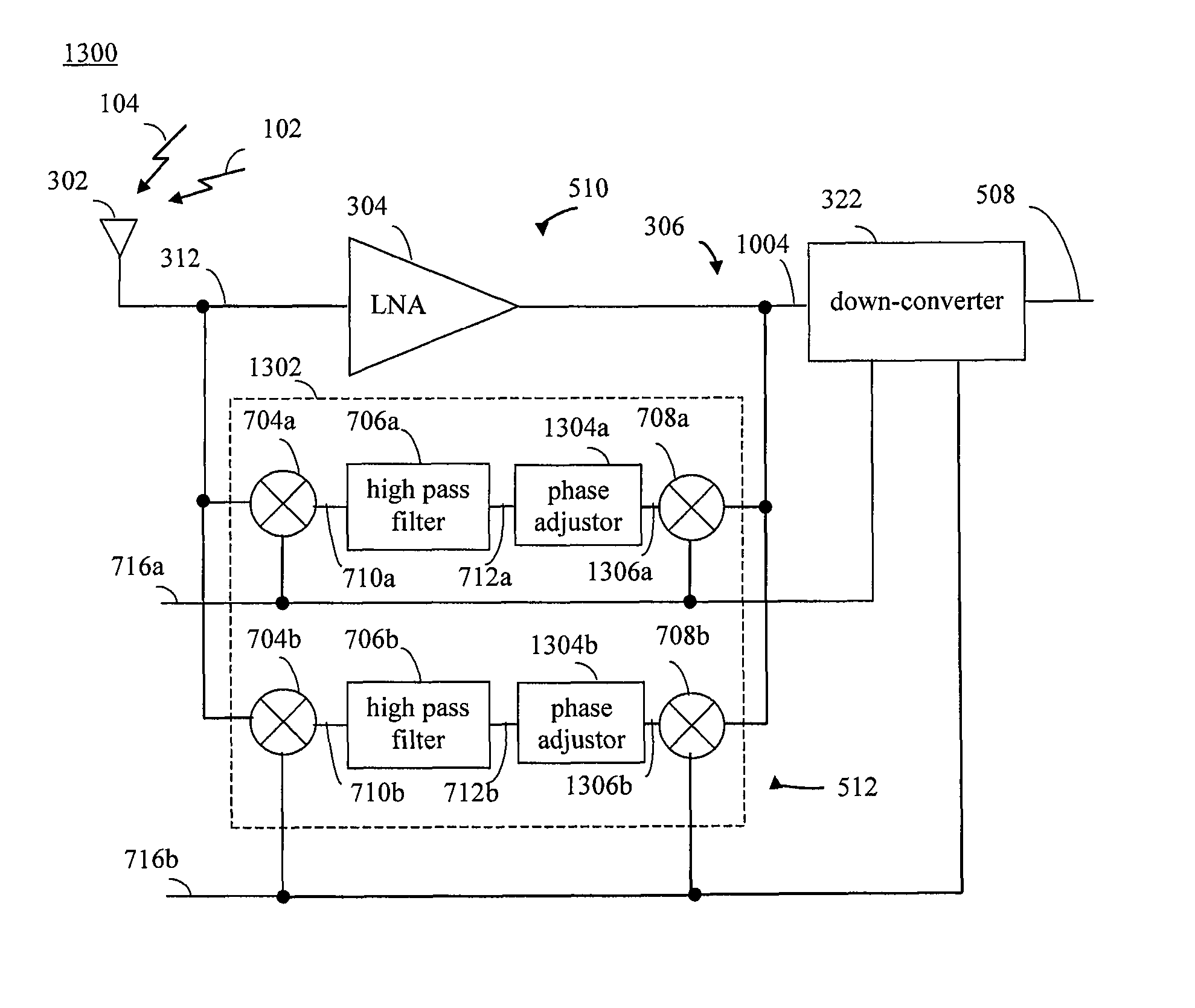
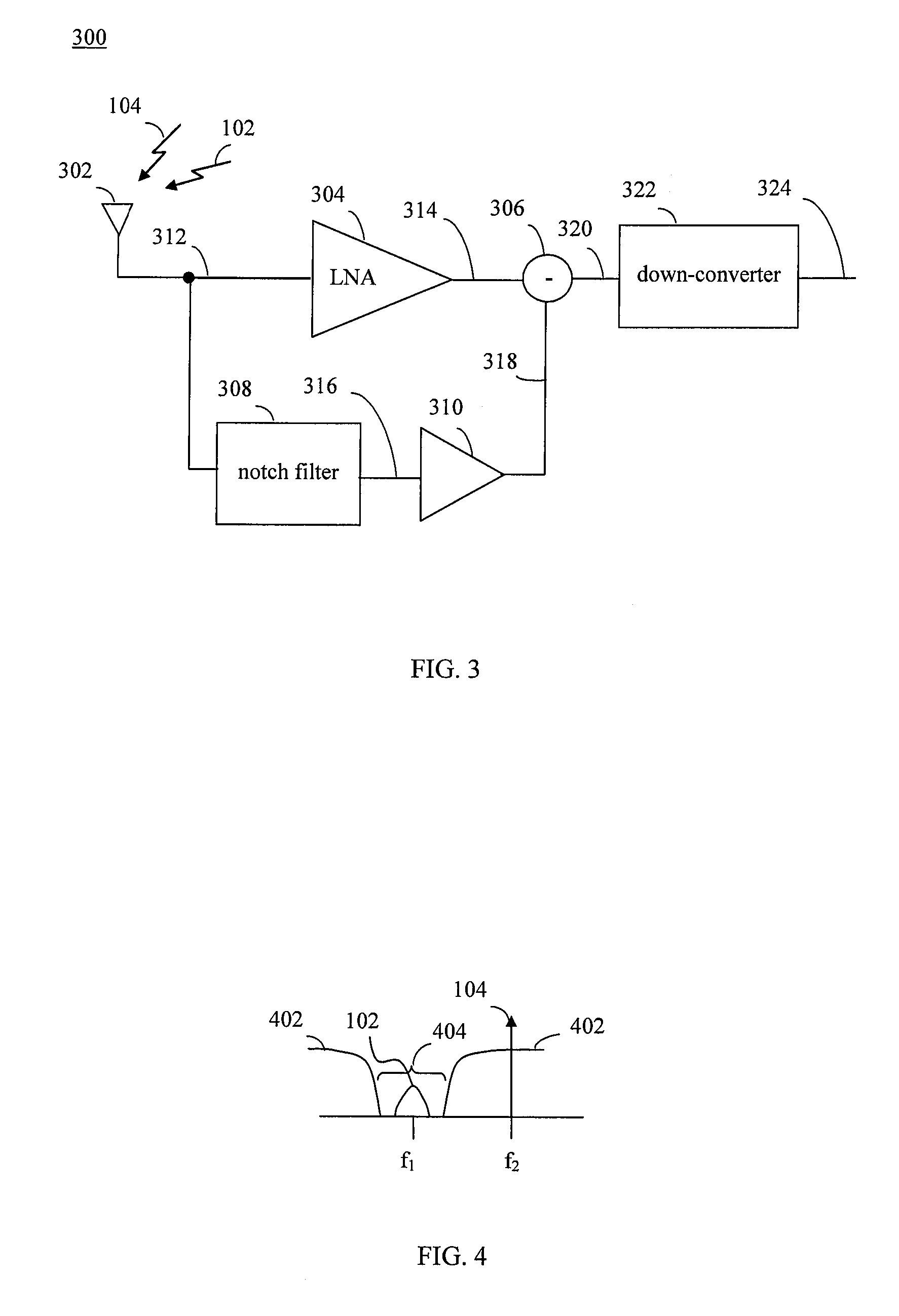
Methods, systems, and apparatuses for filtering received radio frequency signals are provided. A first RF communication signal is received that includes a desired information signal portion and an undesired blocker signal portion that is offset in frequency from the desired portion. The first RF communication signal is amplified in a first signal path and is filtered in a second signal path. The filtering of the first RF communication signal in the second signal path includes: down-converting the first RF communication signal to a down-converted signal, high pass filtering the down-converted signal, and up-converting the high pass filtered down-converted signal to a second RF communication signal. The filtering of the first RF communication signal filters out the desired information signal portion from the second signal path. A signal phase is adjusted in the second signal path to match phase shifts between the first and second signal paths. The second RF communication signal is subtracted from the amplified first RF communication signal to generate a third RF communication signal. Third RF communication signal includes the desired information signal portion but does not include the blocker signal, which is canceled during the subtraction.

Description

BACKGROUND OF THE INVENTION[0001]1. Field of the Invention[0002]The present invention relates to communication systems, and in particular, to the filtering of radio frequency communication signals.[0003]2. Background Art[0004]Wireless communication systems enable the transfer of information over a distance without the use of electrical conductors or wires. Such wireless communication systems typically transmit radio frequency (RF) communication signals that are modulated with information. Varieties of communication standards exist that define attributes of communication signals for use in different applications. For example, a communication signal according to a particular standard may have a defined carrier frequency, one or more defined modulation schemes, a defined error correction scheme, and / or further defined attributes.[0005]A wireless communication system may include one or more transmitters and receivers. A transmitter is used to transmit a RF communication signal, while a ...

Claims


Application Information

Patent Timeline
Patent Type & Authority Patents(United States)
IPC IPC(8): H04B1/10
CPCH04B1/1036H04B1/123H04B1/10H04B1/16
Inventor DARABI, HOOMAN
Owner AVAGO TECH INT SALES PTE LTD
Learn More