Lighting unit and display equipment provided therewith

a technology of display equipment and lighting units, which is applied in the direction of lighting and heating equipment, planar/plate-like light guides, instruments, etc., can solve the problems of limited number of light sources which can be arranged, the thickness of the light-guiding member becomes thicker than the thickness of the light-guiding member, and the obstacle to make the lighting unit small, etc., to achieve high uniformity of illumination light and high brightness.

Active Publication Date: 2011-03-15
PANASONIC LIQUID CRYSTAL DISPLAY CO LTD +1
View PDF14 Cites 42 Cited by
  • Summary
  • Abstract
  • Description
  • Claims
  • Application Information

AI Technical Summary

Benefits of technology

[0016]In the above, according to the present invention, in a lighting unit which uses a light source which is provided with a plurality of light emitting devices, a lighting unit which has high uniformity of illumination light and a narrow frame and is of thin type can be realized. Therefore, the display equipment which uses the lighting unit of the present invention can realize display equipment which has high uniformity of brightness and color of the screen and has a narrow frame and is of thin type.

Problems solved by technology

As this color mixing area becomes an ineffective area from which the illumination light is not outputted, it becomes an obstacle to make the lighting unit small.
On the other hand, in the above-mentioned background technique, there is a problem that the thickness of the light-guiding member becomes thicker than that of the light-guiding member used for the typical edge light type because it is necessary to make it thicker on the reflector side than on the light source side.
Further, as the light source is to be arranged on one terminal surface of the light-guiding member, the number of the light sources which can be arranged is limited.
For this reason, it has a problem that it is difficult to obtain a lighting unit which has the light intensity necessary for realizing light display equipment.
These problems become notable in particular in a lighting unit for a large screen.

Method used


Image

  • Lighting unit and display equipment provided therewith
  • Lighting unit and display equipment provided therewith
  • Lighting unit and display equipment provided therewith

Examples


embodiment 1

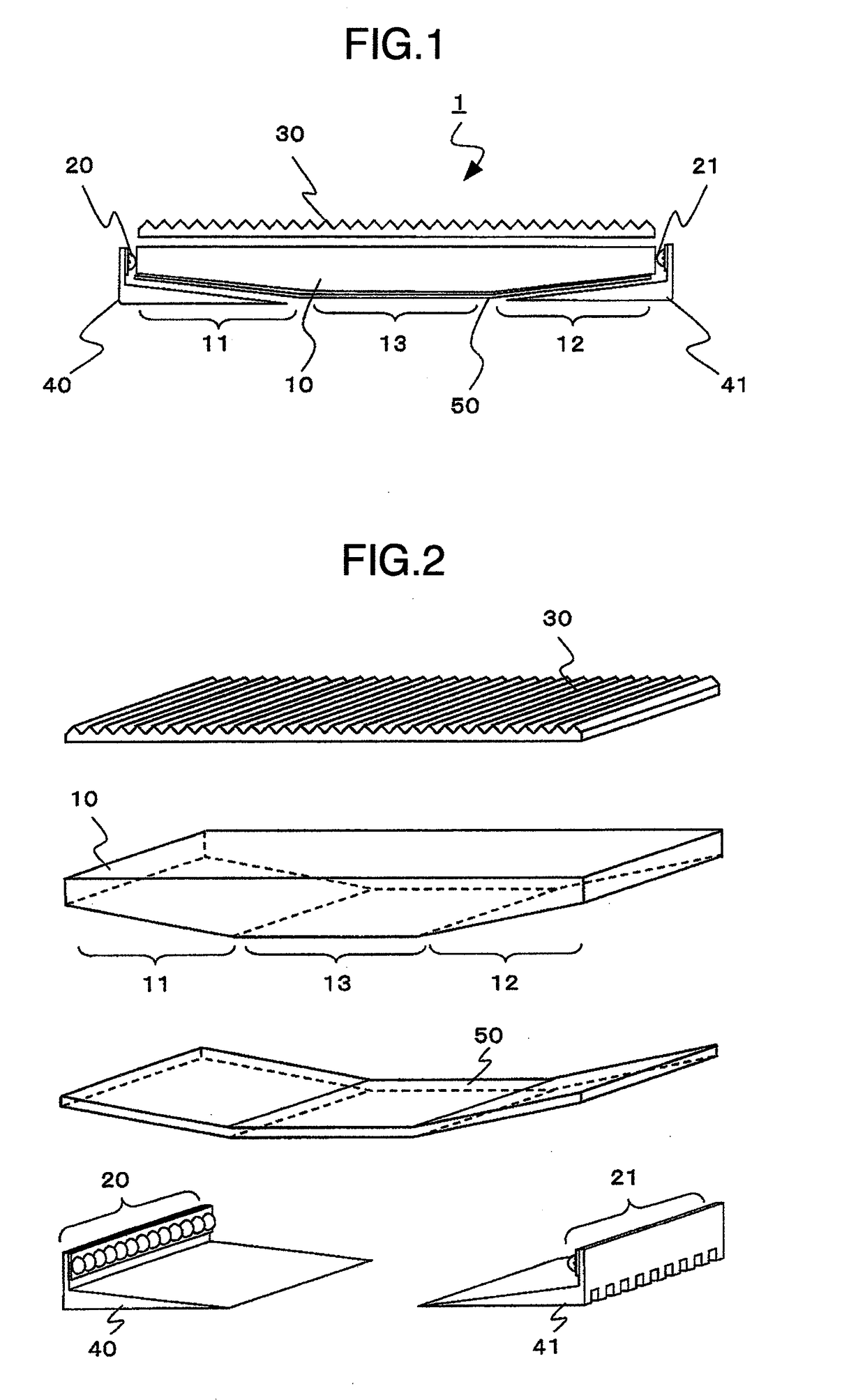
[0031]FIG. 1 shows an example of a lighting unit according to the present invention and is a partial cross section showing a schematic configuration of a main part. And, FIG. 2 is a schematic cross-eyed diagram showing the configuration of the main part of the lighting unit according to the present invention.

[0032]In FIGS. 1 and 2, a lighting unit 1 is arranged on the rear of a display panel not shown which displays the image by adjusting the transmitted light intensity of the light and it is appropriate for the lighting unit which illuminates the display panel from the rear. For the display panel, a display panel which displays the image by adjusting the transmitted light intensity of the light which enters can be used, and in particular, a liquid crystal display panel which has a long lifetime and can conducts a matrix display can be used.

[0033]The lighting unit 1 is configured with a light-guiding member 10, a first light source group 20 and a second light source group 21 which a...

embodiment 2

[0084]Next, it will be explained about the other embodiment of the light-guiding member in the lighting unit according to the present invention. FIG. 10 is a schematic plane diagram to explain the configuration of the light mixing area of the light-guiding member and its vicinity. This light-guiding member has the form of the terminal surface to which a light source group 25 is adjacent being changed compared with the light-guiding member 10 which has been explained referring to FIG. 7. More specifically, the part to which the plurality of light emitting devices configuring the light source group 25 are adjacent is made to be an arc like hollow.

[0085]Namely, in FIG. 10, the lighting unit provided with this light-guiding member 15 has a plurality of arc like hollow parts on the terminal surface of the light-guiding member 15 and arranges one to one the plurality of light emitting devices configuring the light source group in the parts corresponding to their centers. The arc like holl...

embodiment 3

[0089]Next, it will be explained about the other embodiment of the radiating member in the lighting unit according to the present invention. FIG. 11 is a schematic cross-eyed diagram showing a configuration of the main part of the lighting unit according to the present invention. This embodiment is the lighting unit which has been explained referring to FIG. 2 in which the form of the radiating member connected to the light source group is different, and the explanation will be omitted regarding the parts which have already been explained. In FIG. 2 the radiating members are connected to the two light source groups 20, 21 respectively, but here, one radiating member 42 is connected to the two light source groups 20, 21. On this occasion, in the part corresponding to the reverse side of the light mixing areas 11, 12 of the light-guiding member 10, the height of the radiating fin is secured by making the radiating member thicker as it closes to the light source group and the radiation...


PUM


Abstract

A light-guiding member is provided with two light source groups on its both terminals and the light-guiding board comprises two light mixing areas which have a cross section form which is symmetry for its center line, and a light outputting area between these. The light mixing areas function as an area in which the lights from each adjacent light source group are mixed and at the same time function as an area to output the mixed lights from each remote light source group. The light outputting area functions as an area to pass a part of the mixed lights from the two light source groups and at the same time functions as an area to output the rest.

Description

BACKGROUND OF THE INVENTION[0001]The present invention relates to a lighting unit of display equipment which displays an image by adjusting the transmitted light intensity of the light, and in particular, to a lighting unit which uses a light source which has a plurality of different light emitting colors and display equipment provided therewith.[0002]The display equipment is a medium which visually conveys the information to the human, and in the present day which has become a highly information society it is an important existence for the human and the society. The display equipment can be roughly classified in display equipment of emissive type such as CRT (Cathode Ray Tube), PDP (Plasma Display Panel) and the like, and display equipment of non-emissive type such as liquid crystal display equipment, ECD (Electrochromic Display), EPID (Electrophoretic Image Display), and the like.[0003]The display equipment of non-emissive type is the one which displays the image by adjusting the ...

Claims


Application Information

Patent Timeline
Patent Type & Authority Patents(United States)
IPC IPC(8): F21V8/00
CPCG02B6/002G02B6/0068G02B6/0021G02B6/003G02B6/0038G02B6/0048G02B6/0083
Inventor ADACHI, MASAYASUGITA, TATSUYA
Owner PANASONIC LIQUID CRYSTAL DISPLAY CO LTD
Why Eureka
Try Eureka