Dimmer switch with adjustable high-end trim
a high-end trim and switch technology, applied in the direction of switch power arrangement, contact mechanism, instruments, etc., can solve the problem of not having user-accessible means to change the high-end trim
- Summary
- Abstract
- Description
- Claims
- Application Information
AI Technical Summary
Benefits of technology
Problems solved by technology
Method used
Image
Examples
first embodiment
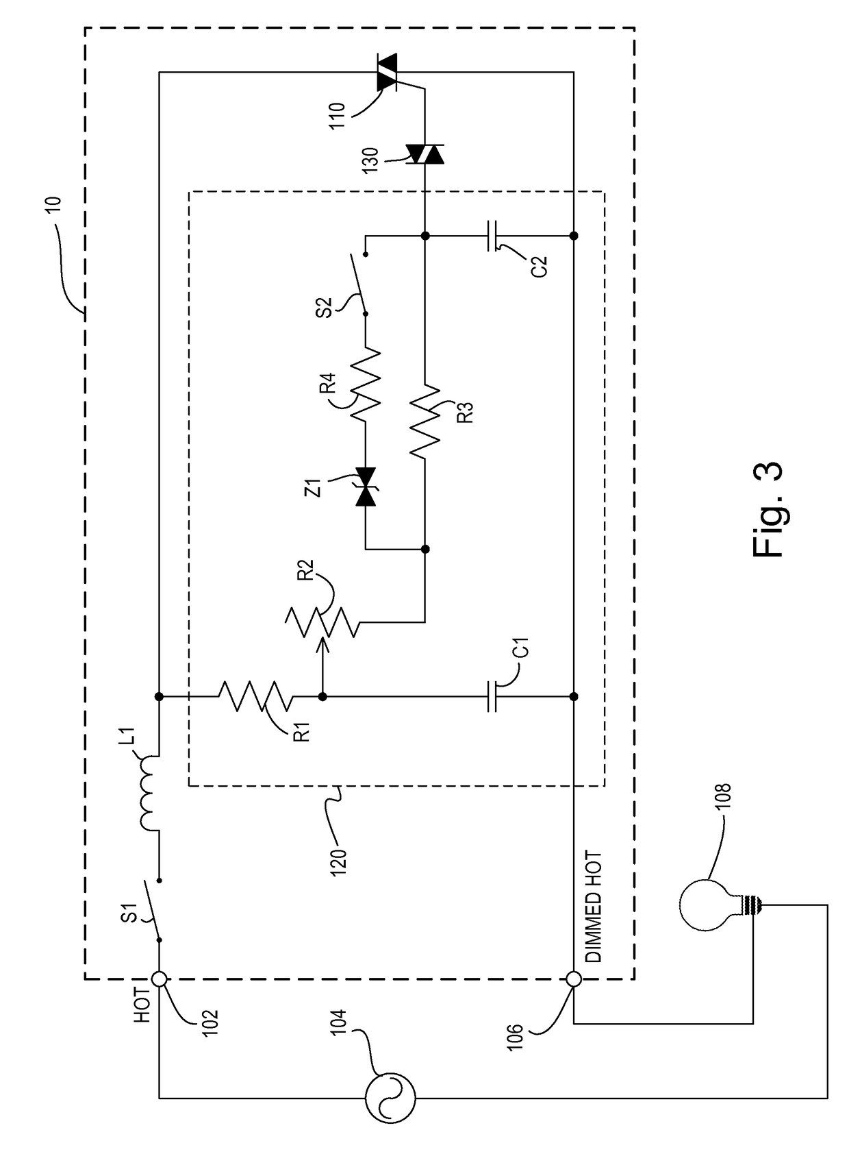
[0026]FIG. 3 is a simplified electrical schematic diagram of the dimmer switch 10 according to the present invention. The dimmer switch 10 includes a hot terminal 102 that is connected to an AC power source 104, and a dimmed hot terminal 106 that is connected to a lighting load 108, such as an electric lamp. The dimmer switch 10 includes a switch S1 connected to the hot terminal 102, a choke L1 connected in series with the switch S1, and a triac 110 connected in series between the choke L1 and the dimmed hot terminal 106. The triac 110 may alternatively be replaced by any suitable bidirectional switch, such as, for example, a field-effect transistor (FET) or an insulated gate bipolar junction transistor (IGBT) in a rectifier bridge, two FETs in anti-series connection, two IGBTs in anti-series connection, or a pair of silicon-controlled rectifiers. The switch S1 is the electrical representation of the rocker switch 12 of the user interface of the dimmer switch 10. When the switch S1 ...
second embodiment
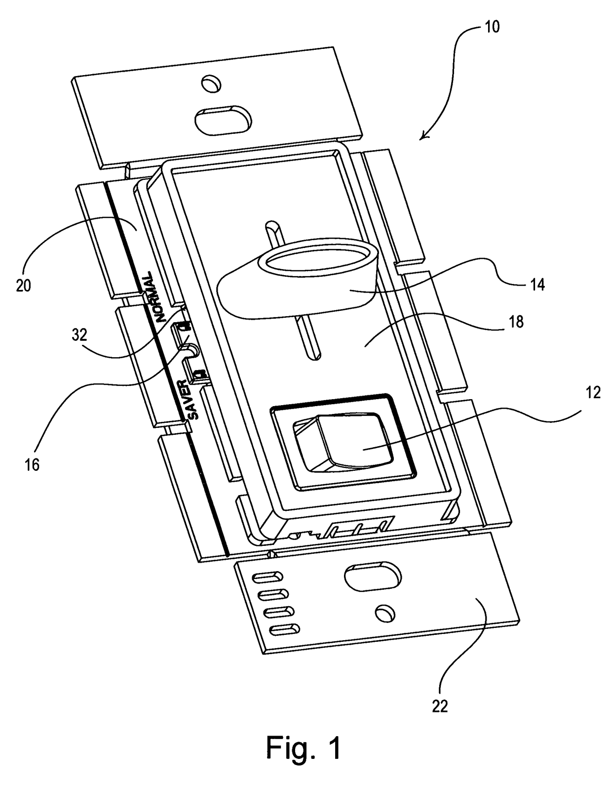
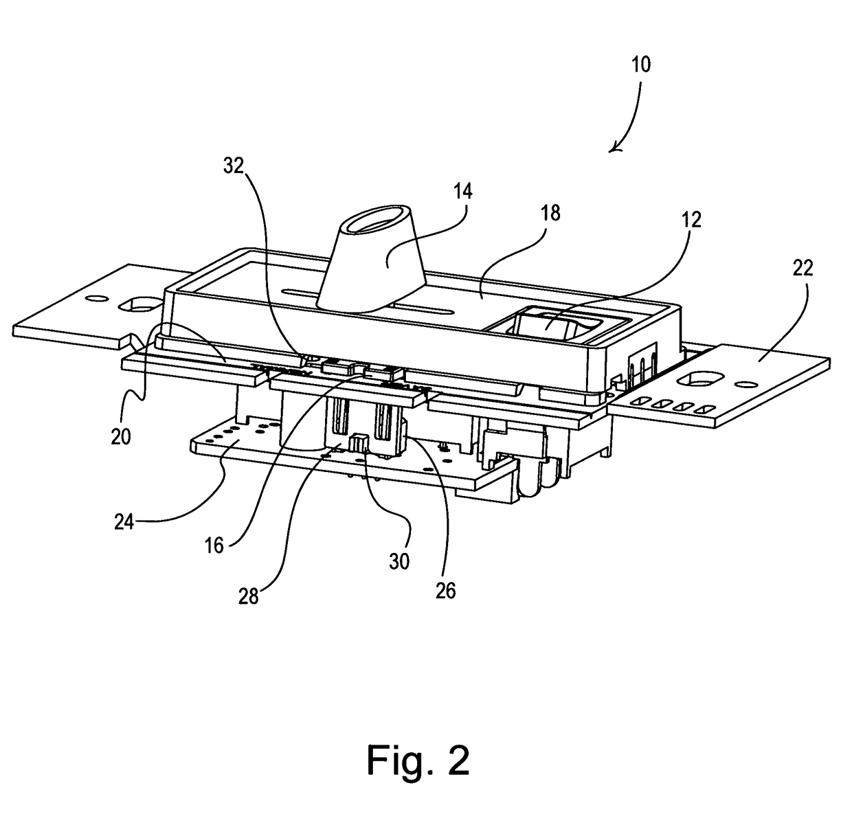
[0038]FIG. 5 is a simplified electrical schematic diagram of a dimmer switch 200 according to the present invention. Rather than including the switch S2, the dimmer switch 200 comprises a potentiometer R5 for adjusting the high-end trim. The potentiometer R5 has a wiper lead that is connected to the second lead of the resistor R4 and a second lead connected to the junction of the resistor R3, the capacitor C2, and the diac 130. Preferably, potentiometer R5 comprises an adjustment member, such as a slider control or a rotary knob, which is provided in an opening in the yoke 22 or between the bezel 18 and the yoke 22 (e.g., the opening 32 shown in FIGS. 1 and 2). The potentiometer R5 preferably has a value that can be varied from a minimum resistance (e.g., approximately 0Ω) up to a maximum value of about 1 MΩ. When the resistance of the potentiometer R5 is substantially 0Ω, the dimmer 200 operates at the first nominal high-end trim level (as does the dimmer 10 of FIG. 3 when the swit...
third embodiment
[0039]FIG. 6 is a simplified electrical schematic diagram of a dimmer switch 300 according to the present invention. The dimmer switch 300 comprises a multi-position switch S2′, having four (4) positions A, B, C, D. Three resistors R6A, R6B, R6C are coupled between the transient voltage suppressor Z1 and the multi-position switch S2′. The transient voltage suppressor Z1 is coupled in series with the first resistor R6A, the second resistor R6B, and the third resistor R6C when the switch S2′ is in the first position A, the second position B, and the third position C, respectively. When the switch S2′ is in the fourth position D, the series combination of the transient voltage suppressor Z1 and the resistor R4 is simply coupled in parallel with the resistor R3. The first resistor R6A has a first resistance, for example, 63 kΩ. The second resistor R6B has a second resistance, smaller than the first resistance, for example, 56 kΩ. The third resistor R6C has a third resistance, smaller th...
PUM
 Abstract
Description
Claims
Application Information
 - R&D
- Intellectual Property
- Life Sciences
- Materials
- Tech Scout
- Unparalleled Data Quality
- Higher Quality Content
- 60% Fewer Hallucinations
Browse by: Latest US Patents, China's latest patents, Technical Efficacy Thesaurus, Application Domain, Technology Topic, Popular Technical Reports.
© 2025 PatSnap. All rights reserved.Legal|Privacy policy|Modern Slavery Act Transparency Statement|Sitemap|About US| Contact US: help@patsnap.com


