Molded ferrite sheet, sintered ferrite substrate and antenna module

a technology of sintered ferrite and substrate, applied in the direction of magnetic bodies, record information storage, synthetic resin layered products, etc., can solve the problems of contaminating electronic precision components, affecting the quality of the antenna, and affecting the performance of the antenna

Active Publication Date: 2011-03-22
TODA IND
View PDF11 Cites 9 Cited by
  • Summary
  • Abstract
  • Description
  • Claims
  • Application Information

AI Technical Summary

Benefits of technology

[0008]An object of the present invention is to provide a molded ferrite sheet which permits the preparation of clean and thin sintered ferrite substrates which are not stuck to each other or to the sintering table even without a releasing powder such as zirconia powder or alumina powder. Another object of the present invention is to provide a clean sintered ferrite substrate free of residual releasing powder which may contaminate electronic devices.
[0009]Some antennas for use in the vicinity of a metal component are provided in advance with a magnetic sheet or the like for tuning it to a desired frequency. However, when such an antenna is placed in the vicinity of the metal component, the resonant frequency of the antenna is changed. Thus, the antennas must be tuned to a desired frequency after they have been incorporated in electronic devices. It is, therefore, a further object of the present invention to eliminate such a laborious procedure and to provide a thin antenna module which has a specific frequency that has been previously adjusted after mounting a magnetic member and which does not undergo any significant change in its frequency even when placed in the vicinity of a metal component.
[0010]It is yet a further object of the present invention to eliminate the instability of the antenna characteristics of an antenna for use in the vicinity of a metal component which has been hitherto caused by the presence of gaps formed between a magnetic member and a metallic shield plate.

Problems solved by technology

When the stuck sintered ferrite substrates are peeled from each other or removed from the sintering table, the sintered ferrite substrates may be damaged.
This procedure is very troublesome.
In addition, the releasing powder is difficult to remove completely from the sintered ferrite substrates and thus may contaminate the electronic precision components in which the sintered ferrite substrates are used.
The method in which the ferrite sheet is used to prevent deformation of a ferrite core is low in productivity.
In addition, the use of such an additional ferrite sheet is not desirable from the standpoint of cost.
The method using an underlying powder, on the other hand, has a problem because, especially when the molded ferrite sheets to be sintered are thin, the obtained sintered ferrite substrates are apt to undulate or break due to physical contact of the substrates with aggregates of the powder formed thereunder during sintering or some other reasons.
This approach is, however, impractical since it is difficult to arrange the ferrite pieces regularly on a sheet substrate in an efficient manner.
This is a major problem in practical applications.
However, it is difficult to reduce the thickness of an antenna module of this type, and the recent demand for size reduction of electronic devices cannot be satisfied.

Method used


Image

  • Molded ferrite sheet, sintered ferrite substrate and antenna module
  • Molded ferrite sheet, sintered ferrite substrate and antenna module
  • Molded ferrite sheet, sintered ferrite substrate and antenna module

Examples


example 1

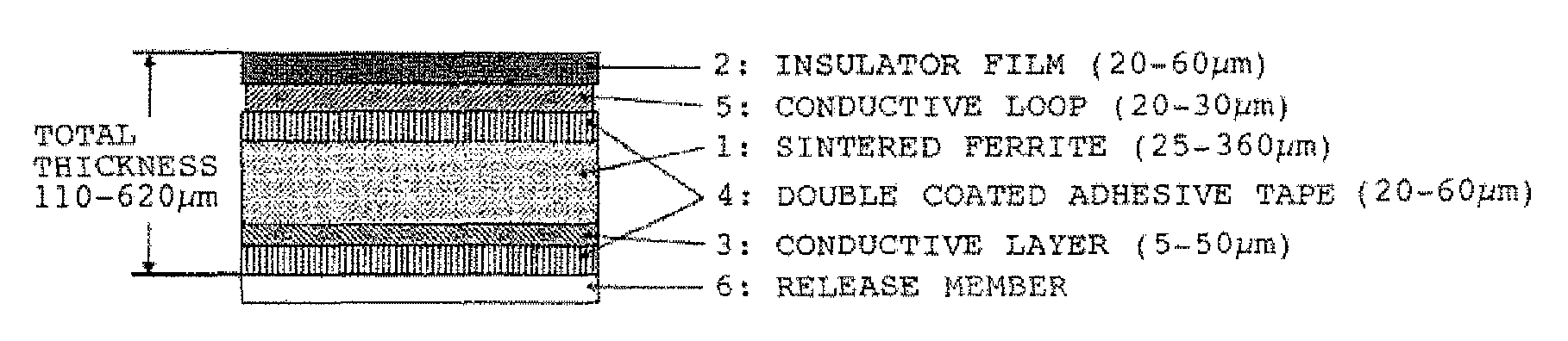
[0125]Using a pressure kneader, 1,000 parts by weight of a ferrite powder, obtained by surface-treating 1,000 parts by weight of Ni—Zn—Cu ferrite powder (composition: Fe2O3: 48.5 mol %, NiO: 20.5 mol %, ZnO: 20.5 mol %, CuO: 10.5 mol %; calcinations conditions: 850° C., 90 minutes; cumulative 50% volume diameter: adjusted to 0.7 μm) with 10 parts by weight of a titanate-based coupling agent (KR-TTS manufactured by Ajinomoto Co., Inc.), 50 parts by weight of a thermoplastic elastomer (LUMITAC 22-1 manufactured by Tosoh Corporation), 100 parts by weight of polyethylene having a density of 0.9 g / cm3 and 20 parts by weight of stearic acid were kneaded at 130° C. for 40 minutes. The thus obtained kneaded mass of a ferrite resin composition was press molded at a temperature of 160° C. under a pressure of 100 kg / cm2 for a pressurization time of 3 minutes using an iron plate, which had been sandblasted to have a center line average roughness of 450 nm and a maximum height of 8 μm, to obtain...

example 2

[0127]Using a ball mill, 100 parts by weight of the same Ni—Zn—Cu ferrite as used in Example 1, 2 parts by weight of butyl phthalyl butyl glycolate, 12 parts of a polyvinylalcohol resin (ESLEK B BM-1 manufactured by Sekisui Chemical Co., Ltd.) and 60 parts by weight of a mixed solvent composed of 4 parts of n-butanol and 6 parts of toluene were mixed, dissolved or dispersed to obtain a ferrite-dispersed coating liquid. The ferrite-dispersed coating liquid was defoamed by an oil rotary vacuum pump and uniformly applied with a doctor blade to a PET film (LUMIMAT 50S200 TRES manufactured by Panak Co., Ltd.), one side of which had been sandblasted to have a center line average roughness of 530 nm and a maximum height of 5.6 μm, to a given thickness. The coating was dried with hot wind at 100° C. for 30 minutes to obtain a molded ferrite sheet having a thickness of 204 μm. The molded ferrite sheet was cut into squares of side 100 mm. Each of the cut sheets was peeled off from the PET fil...

example 3

[0129]A kneaded mass of a ferrite resin composition was prepared in the same manner as that in Example 1 except that a mixture of 300 parts by weight of Ni—Zn—Cu ferrite powder (composition: Fe2O3: 48.5 mol %, NiO: 20.5 mol %, ZnO: 20.5 mol %, CuO: 10.5 mol %; calcination conditions: 1,000° C., 90 minutes; cumulative 50% volume diameter: 6 μm) and 700 parts by weight of the same Ni—Zn—Cu ferrite powder (cumulative 50% volume diameter: 0.7 μm) as used in Example 1 was used. The thus obtained kneaded mass was press molded at a temperature of 160° C. under a pressure of 100 kg / cm2 for a pressurization time of 3 minutes using an iron plate, which had been processed to have a center line average roughness of 120 nm and a maximum roughness of 2 μm, to obtain a molded ferrite sheet having a thickness of 200 μm and an outer size of 100 mm. Using the thus obtained sheet, sintered ferrite substrates were prepared in the same manner as that in Example 1. The obtained sintered ferrite substrate...


PUM

PropertyMeasurementUnit
thicknessaaaaaaaaaa
roughnessaaaaaaaaaa
heightaaaaaaaaaa

Abstract

The present invention relates to a molded ferrite sheet having opposing surfaces and a thickness in a range of 30 μm to 430 μm, at least one surface of said opposing surfaces having the following surface roughness characteristics (a) to (c):(a) a center line average roughness is in a range of 170 nm to 800 nm,(b) a maximum height is in a range of 3 μm to 10 μm, and(c) an area occupancy rate of cross-sectional area taken along a horizontal plane at a depth of 50% of the maximum height in a square of side 100 μm is in a range of 10 to 80%.

Description

[0001]This application claims priority to JP 2007-057892 filed Mar. 7, 2007 and JP 2007-282576 filed Oct. 31, 2007, the entire contents of each of which are hereby incorporated by reference.BACKGROUND OF THE INVENTION[0002]The present invention relates to a molded ferrite sheet for use in preparing a thin single-layer soft magnetic sintered ferrite substrate, to a thin single-layer soft magnetic sintered ferrite substrate, and to an antenna module for a noncontact IC tag using RFID (Radio Frequency Identification) technology.[0003]In the fabrication of sintered ferrite substrates, a plurality of superposed molded sheets of a ferrite powder or a mixture of a ferrite powder and a resin are sintered at a time. In this case, the resulting sintered ferrite substrates tend to stick or bond to each other and / or to the sintering table on which they are supported during sintering. When the stuck sintered ferrite substrates are peeled from each other or removed from the sintering table, the s...

Claims


Application Information

Patent Timeline
Patent Type & Authority Patents(United States)
IPC IPC(8): B32B9/04
CPCC04B35/2625C04B35/265C04B2235/3206C04B2235/3279C04B2235/3281C04B2235/3284C04B2235/5436C04B2235/5445C04B2235/963H01F1/344H01F41/16H01Q7/06C04B35/62218C04B35/63408C04B2235/3234C04B2235/602C04B2235/6025C04B2235/77C04B2235/945H01Q17/00Y10T428/24355Y10T428/31609C04B35/26H01F1/04H01F1/34H01Q1/24
Inventor KIMURA, TETSUYADOTE, TOMOHIROYAMAMOTO, KAZUMIDOI, TAKANORIOKANO, YOJI
Owner TODA IND
Why Eureka
Try Eureka