Image processing apparatus and control method therefor

a technology of image processing and control method, applied in the direction of electrical apparatus, instruments, computing, etc., can solve the problems of unnatural boundaries and noticeable effects, and achieve the effect of high compression ratio

Inactive Publication Date: 2011-03-22
CANON KK
View PDF13 Cites 8 Cited by
  • Summary
  • Abstract
  • Description
  • Claims
  • Application Information

AI Technical Summary

Benefits of technology

[0008]The present invention therefore provides a technique which suppresses mixing of different types of encoded data in an image area having a specific image property like that described above while allowing mixing of losslessly encoded data and lossily encoded data, and can also obtain a high compression ratio by performing lossy encoding with respect to an image after resolution conversion.
[0014]According to the present invention, mixing of different types of encoded data is suppressed in an image area having a specific image property while mixing of losslessly encoded data and lossily encoded data is allowed, and a high compression ratio can be obtained by performing lossy encoding with respect to an image after resolution conversion.

Problems solved by technology

On the other hand, when a losslessly encoded block is adjacent to a lossily encoded block, the boundary looks unnatural and becomes noticeable.

Method used


Image

  • Image processing apparatus and control method therefor
  • Image processing apparatus and control method therefor
  • Image processing apparatus and control method therefor

Examples


first embodiment

Modification of First Embodiment

[0074]The first embodiment has been described on the basis of the arrangements shown in FIGS. 1 and 3, but equivalent processing can be implemented by software. An example of this will be described below.

[0075]FIG. 7 is a block diagram showing the arrangement of an information processing apparatus such as a personal computer. Referring to FIG. 7, reference numeral 1 denotes a CPU which controls the overall apparatus; 2, a ROM storing a BIOS and a boot program; 3, a RAM which is used as a work area for the CPU 1; 4, a hard disk drive (HDD) which stores an OS (Operating System) and application programs associated with image encoding processing / decoding processing; 5, a keyboard; 6, a pointing device such as a mouse; and 7, a display control unit which incorporates a video memory for rendering an image to be displayed and a video controller which renders an image in the video memory under the control of the CPU 1, reads an image from the video memory, an...

second embodiment

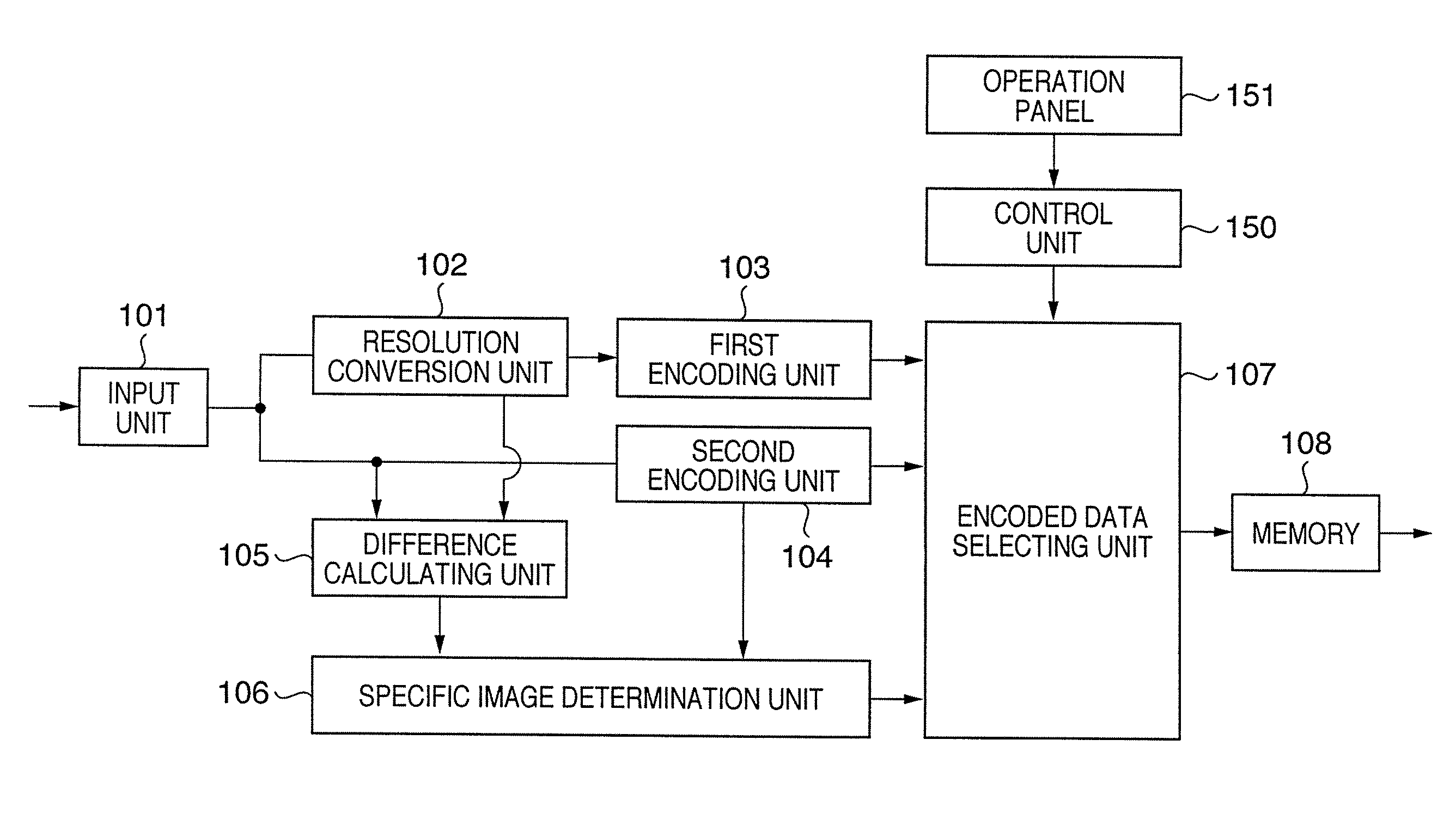
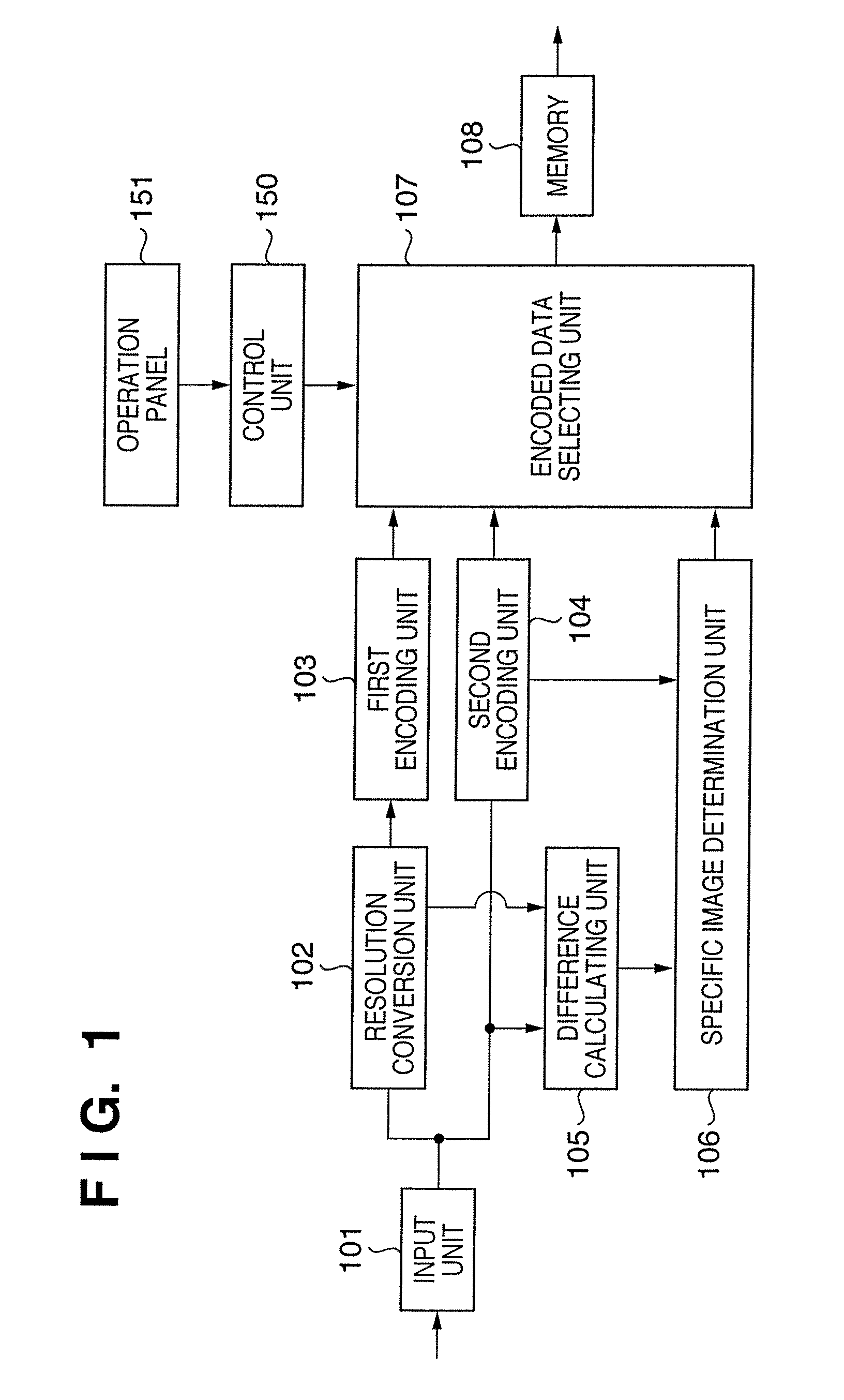
[0095]FIG. 10 is a block diagram showing the arrangement of an image processing apparatus according to the second embodiment. The same reference numerals as in FIG. 10 denote elements having the same functions in FIG. 1. Assume that a memory 108′ has a sufficient capacity for the storage of one-page encoded data. In addition, an input unit 101′ performs re-input operation from the start of one page in response to an instruction signal from a control unit 150′ even in the middle of encoding processing of one page.

[0096]The input unit 101′ in the second embodiment will be described as a unit which inputs image data from a renderer which generates an output image in accordance with print data or the description of a document file.

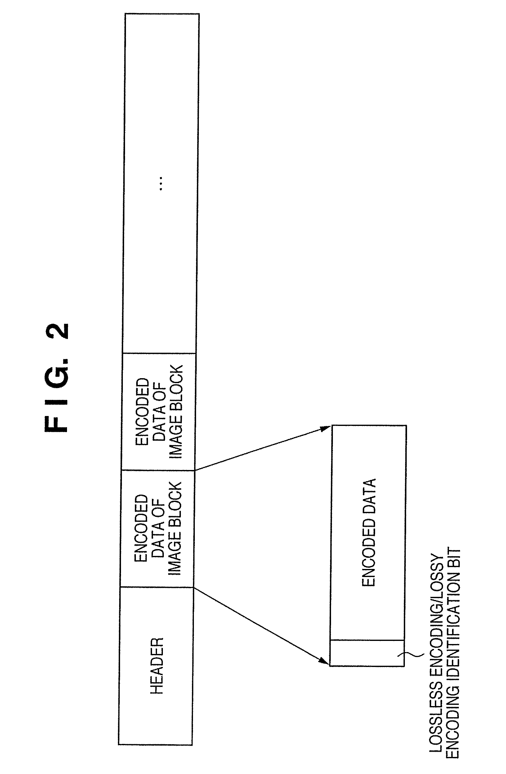
[0097]When outputting the encoded data of an image block to the memory 108′, an encoded data selecting unit 1071 notifies the control unit 150′ of information indicating the code amount of the encoded data.

[0098]A first encoding unit 103′ performs lossy encodi...

third embodiment

[0119]Assume that in the third embodiment, the upper limit value of the amount of image data after compression is determined as in the second embodiment.

[0120]An image processing apparatus characterized by performing code amount control by changing the determination condition for a specific image area if the code amount of image data exceeds the upper limit value will be described.

[0121]For example, some type of application (typically, Office 2003 PowerPoint (registered trademark) available from Microsoft, U.S.A.) allows to select a transparency at the time of execution of semitransparency processing. Assume that the transparency is high. In this case, even if a halftone dot pattern is overlaid on a given image, a background image can be clearly seen. Assume that the transparency is low. In this case, when a halftone dot pattern is overlaid on a given image, since a background image portion is not emphasized much, a large change in image quality does not occur even if subsampling or...


PUM


Abstract

This invention suppresses mixing of different types of encoded data in an image area having a specific image property while allowing mixing of losslessly encoded data and lossily encoded data. For this purpose, an input unit inputs image on an image block basis. A conversion unit converts the resolution of the image data to ½ by generating one pixel from 2×2 pixels. A first encoding unit lossily encodes the converted image data. A second encoding unit losslessly encodes the image data for each image block. A selecting unit selects encoded data with a smaller code amount. A determination unit determines whether an image block of interest has a specific image property, and outputs the determination result to the selecting unit. If the image of interest has a specific image property, the selecting unit selects and outputs encoded data of the type set by a control unit in advance.

Description

BACKGROUND OF THE INVENTION[0001]1. Field of the Invention[0002]The present invention relates to an image processing apparatus and method which detect a specific image area in which a noticeable deterioration in image quality is caused by subsampling or the like, selecting an encoding scheme most suitable for the detected area, and encoding the area.[0003]2. Description of the Related Art[0004]Encoding techniques which are used to compress the amount of image data are roughly classified into two types, that is, a lossless encoding technique with little loss of information due to compression / decompression and a lossy encoding technique with a deterioration in image quality due to compression / decompression. In general, lossy encoding provides a higher compression ratio than lossless encoding, and allows adjusting the amount of code generated by changing the degree of deterioration in image quality.[0005]Conventionally, there has been available a method comprising lossless and lossy en...

Claims


Application Information

Patent Timeline
Patent Type & Authority Patents(United States)
IPC IPC(8): G06K9/36H04N1/413H04N19/00H04N19/12H04N19/134H04N19/136H04N19/146H04N19/167H04N19/176H04N19/196H04N19/59H04N19/86H04N19/90
CPCH04N19/176H04N19/15H04N19/17H04N19/12H04N19/186H04N19/647
Inventor MATSUMOTO, YUKI
Owner CANON KK
Why Eureka
Try Eureka