
Orientation optimization method of 2-pin logic cell

a logic cell and orientation optimization technology, applied in the field of determining the orientation of a 2pin logic cell, can solve the problems of difficult to properly adjust the orientation of the cells, the connection between cells is quite complicated, and the current computer-aided design tool does not involve optimizing the orientation of a 2-bin logic cell to further reduce propagation delay and routing length

Active Publication Date: 2011-03-22
RDC SEMICON CO LTD
View PDF1 Cites 1 Cited by
  • Summary
  • Abstract
  • Description
  • Claims
  • Application Information

AI Technical Summary

Benefits of technology

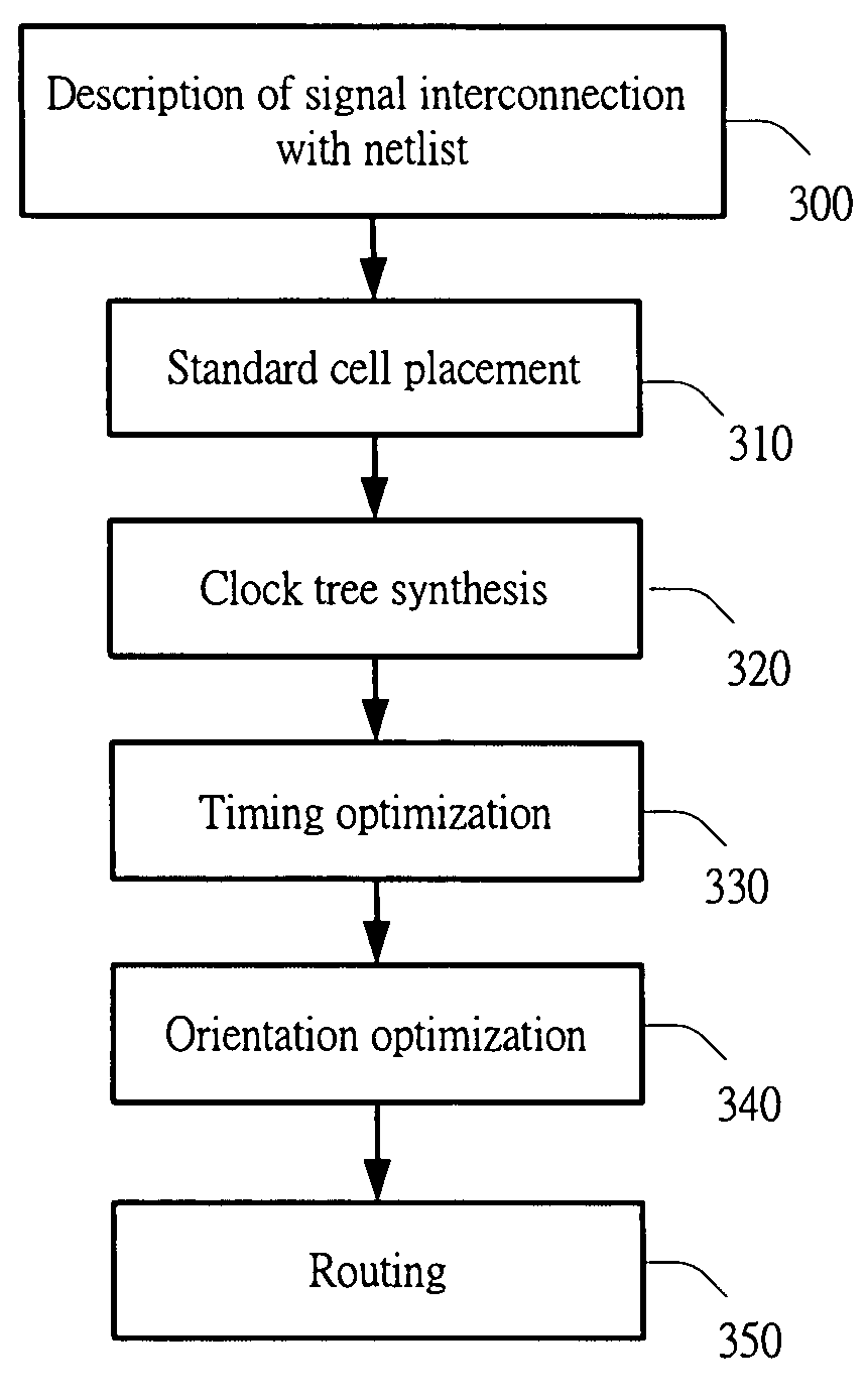
"The present invention provides an orientation optimization method to determine an optimal flipping condition for 2-pin logic cells in a circuit design. This method involves locating signal paths and setting the output of one cell to attract the input of the next cell, thereby flipping the next cell. The invention also includes a physical design method that includes establishing a netlist, performing placement and timing optimization, and performing orientation optimization based on paths-based flip to optionally flip cells. The 2-pin logic cells can be inverters, buffers, or delay elements. The technical effects of the invention include improving the performance and efficiency of circuit designs."

Problems solved by technology

However, none of the current computer-aided design tools involves optimized orientation of 2-bin logic cells to further reduce propagation delay and routing length.
The connection among cells is quite complicated.
Therefore, it is a challenge to properly adjust the orientation of the cells.
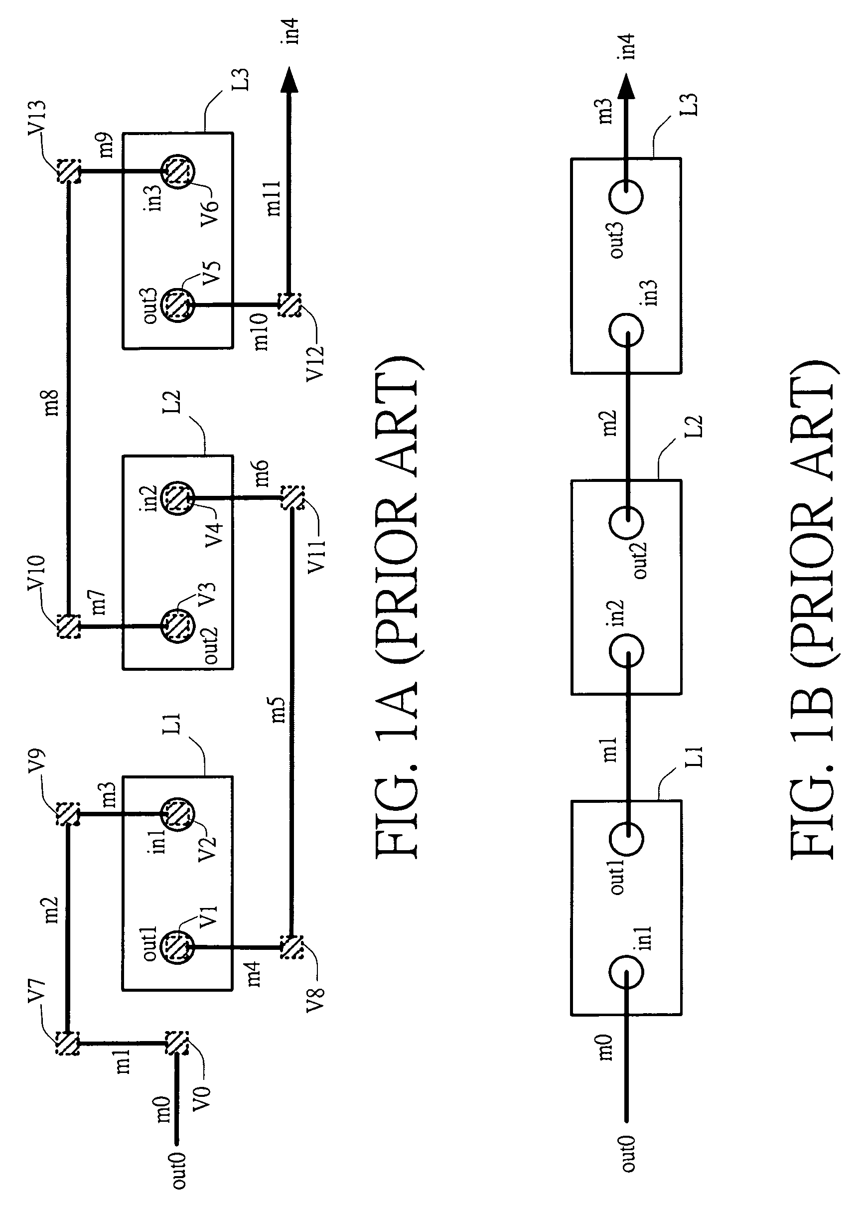
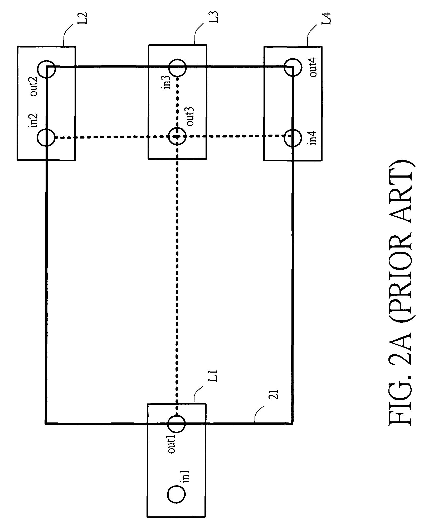
Nevertheless, the conventional “nets-based flip” methods have difficulties in dealing with a situation that signal transmission is implemented with branched paths so that the conventional “nets-based flip” methods could not accurately determine the 2-pin logic cell in which stage is to be flipped.
Therefore, it is improper to determine that a 2-pin logic cell should not be flipped simply due to the increasing size of the associated net bounding box in next stage.

Method used


Image

  • Orientation optimization method of 2-pin logic cell
  • Orientation optimization method of 2-pin logic cell
  • Orientation optimization method of 2-pin logic cell

Examples


Embodiment Construction

[0050]The present invention will now be described more specifically with reference to the following embodiments. It is to be noted that the following descriptions of preferred embodiments of this invention are presented herein for purpose of illustration and description only; it is not intended to be exhaustive or to be limited to the precise form disclosed.

[0051]According to an orientation optimization method of the present invention, a “paths-based flip” algorithm is adopted. For all 2-pin logic cells including inverters, buffers and delay cells, the “paths-based flip” orientation optimization method applies.

[0052]Please refer to FIG. 4. A simple circuitry is exemplified to describe the “paths-based flip” orientation optimization method according to an embodiment of the present invention. The routing starts from a signal source s0 and extends through three 2-pin logic cells L1, L2 and L3 in sequence, thereby constituting a signal chain path I. For attracting inputs (in1, in2, in3)...


PUM


Abstract

In an orientation optimization, at least one signal chain path starting from a signal source and passing through a series of M 2-pin logic cells is located according to a netlist. An output of the Nth 2-pin logic cell in the series of M 2-pin logic cells, where N<M, is set as a gravity point to attract an input of the (N+1)th 2-pin logic cell, thereby optionally flipping the (N+1)th 2-pin logic cell.

Description

FIELD OF THE INVENTION[0001]The present invention relates to a method for determining orientation of a 2-pin logic cell, and more particularly to a method for determining an optimal orientation of a 2-pin logic cell disposed in a signal chain path for obtaining a physical circuit corresponding to an IC design.BACKGROUND OF THE INVENTION[0002]In an IC design flow based on a cell-based library, hardware descriptions such as Verilog's netlist are used to describe involving standard logic cells and nets. The netlist is then processed for physical design. Meanwhile, 2-pin logic cells are commonly used in the physical design for specific circuitry requirements and integrated signal transmission.[0003]A generally adopted placement stage of IC logic cells includes placement of standard logic cells based on a timing driven strategy and a wire-length driven strategy.[0004]In the so-called timing driven strategy, signal path delay time indicative of a duration when a signal is transmitted from...

Claims


Application Information

Patent Timeline
Patent Type & Authority Patents(United States)
IPC IPC(8): G06F17/50
CPCG06F17/5072G06F30/392
Inventor SHIH, YING-ANCHEN, HUNG-MING
Owner RDC SEMICON CO LTD
Learn More