Method for drying a printing ink on a printing substrate in a printing press, and a printing press

a printing press and printing substrate technology, applied in printing presses, office printing, printing, etc., can solve the problems of increasing the environmental impact, time-consuming to dry a processed printing substrate, printing ink being set, etc., and achieve the effect of facilitating the drying of printing ink

Inactive Publication Date: 2011-03-29
HEIDELBERGER DRUCKMASCHINEN AG
View PDF38 Cites 12 Cited by
  • Summary
  • Abstract
  • Description
  • Claims
  • Application Information

AI Technical Summary

Benefits of technology

[0013]An object of the present invention is to devise a method for drying a printing ink on a printing substrate in a printing press, as well as a printing press, which will facilitate the drying of printing ink on the printing substrate used for printing in the printing press.
[0014]In accordance with the present invention, the method for drying a printing ink on a printing substrate in a printing press includes at least the following steps: The printing substrate is conveyed along a path through the printing press. At a first position of the path, at least one printing ink, in particular a solvent-containing printing ink, is printed on the printing substrate. At a second position, a treatment agent is applied to the printing substrate to accelerate the drying of the printing ink on the printing substrate. In other words, the treatment agent is used as a catalyst to accelerate the drying of the printing ink on the printing substrate or to accelerate the absorption of energy, in particular as a direct catalyst, which reduces the energy absorption required for drying the printing ink.
[0015]The use of a treatment agent advantageously eliminates the need for modifying the formulations of the printing inks, in particular of the solvent-containing printing inks, used to accelerate the drying. For that reason, standard printing inks may be used. The dosage and composition of the treatment agent is to be selected as a function of the printing substrate material, of the printing ink to be used in printing, and of the processing parameters, application parameters, or process parameters. The optimal goal is a maximum possible drying of the printing ink on the printing substrate as soon as the printing substrate exits the printing press, thus upon delivery of sheet-type printing substrates or, in the case of web-shaped printing substrates, upon entry into the folder. It is advantageously possible to adapt the particular treatment agent to the printing substrate used; the speed of action of the treatment agent may be adjusted to the properties of the printing substrate, the printing press, and the printing inks in a manner that is specific to processing parameters.

Problems solved by technology

Depending on the particular print job, the prescribed combinations of printing substrate and printing ink are often not coordinated with respect to the drying process, so that it is time-consuming to dry a processed printing substrate.
It may be that the risk of printing ink being set off in delivery can be countered by increasing the spray powder application in a stack, however this increases the environmental impact.
Moreover, one still has to contend with considerable delays until the printed products or signatures can be further processed.
The disadvantage here is that a direct, substantially uncontrolled reaction takes place immediately during the printing process.
Thus, for example, printing ink can even dry in an unwanted manner on the printing cylinder and soil the print unit.
Here, the disadvantage is, however, that an additional system component must be separately provided for the printing press.
The drawback of such drying devices in the infrared region is that a considerable proportion of the energy absorption takes place in the paper, the ink only being indirectly heated.
A rapid drying is only possible by inputting enough energy.
In the process, however, there is the danger, inter alia, of the printing substrate drying out unevenly and becoming warped.
However, the simple knowledge of the window in the paper absorption spectrum cannot be directly exploited in printing technology that uses solvent-containing printing inks, since, as described above, there are other underlying chemical and / or physical drying processes.

Method used


Image

  • Method for drying a printing ink on a printing substrate in a printing press, and a printing press
  • Method for drying a printing ink on a printing substrate in a printing press, and a printing press
  • Method for drying a printing ink on a printing substrate in a printing press, and a printing press

Examples


Embodiment Construction

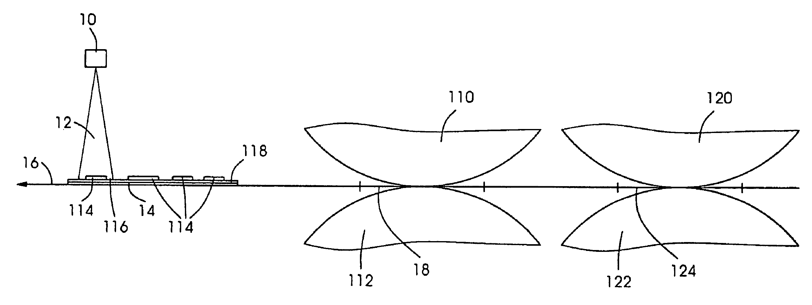
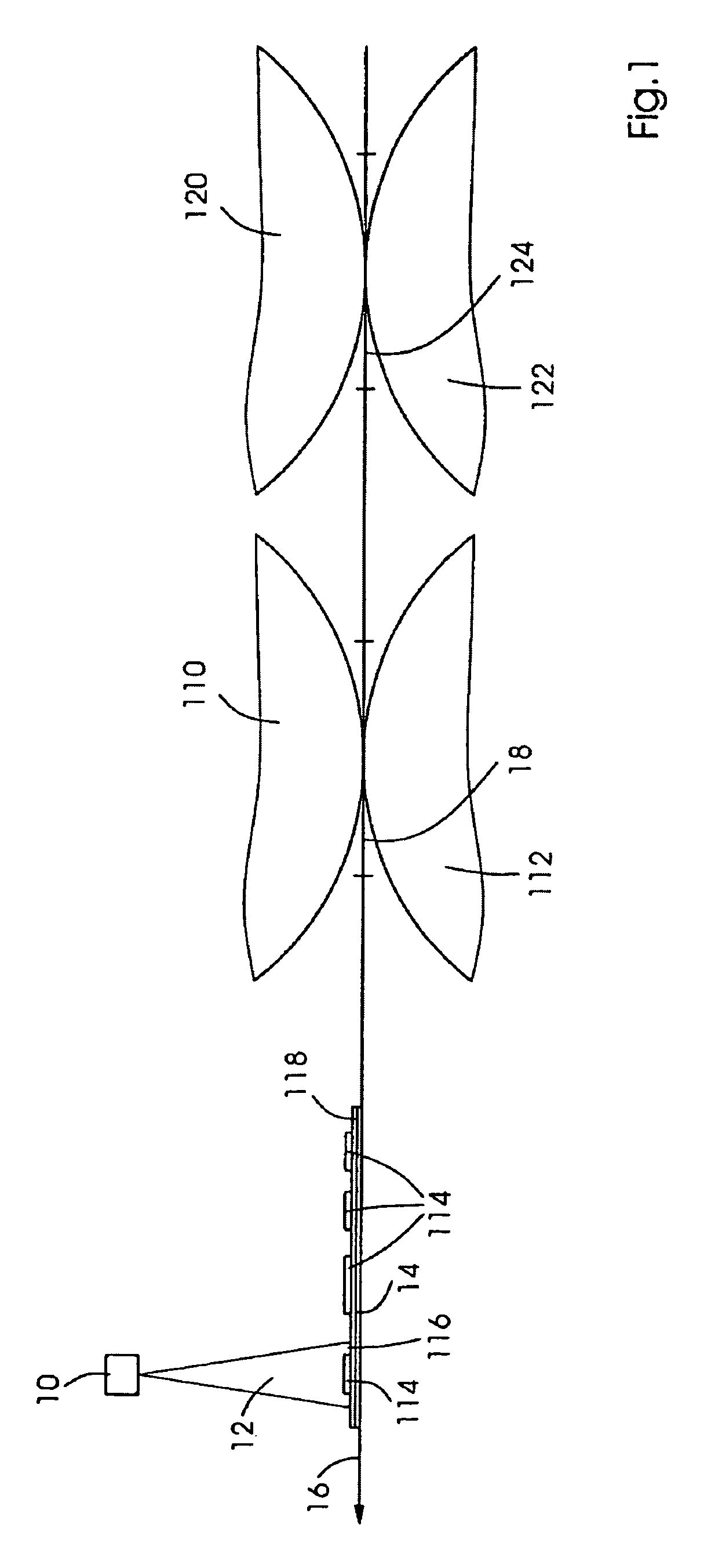
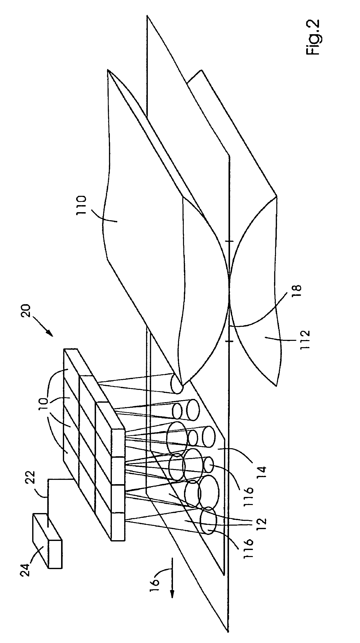
[0044]FIG. 1 shows a schematic representation for elucidating a specific embodiment of the drying method according to the present invention. A radiant energy source 10, in particular a laser, preferably a diode laser or solid-state laser, is configured within a planographic printing press in such a way that light 12 emitted by it is incident to a printing substrate 14 along its path 16 through the planographic printing press at a third position 116, which is situated downstream from a first position 18, in this case a printing nip. While in FIG. 1, printing substrate 14 is shown exemplarily in a sheet shape, the printing substrate may also be guided in a web shape through the planographic printing press. The orientation of path 16 of printing substrate 14 is characterized by an arrow. The path shown here is linear, but is not restricted thereto, and may likewise take a generally curve-shaped or non-linear course, in particular a circular arc. First position 18, here the printing nip...


PUM


Abstract

A method for drying a printing ink (114) on a printing substrate (14) in a printing press (30), and a printing press (30). The printing substrate (14) is moved along a path (16) through the printing press (30) and printed on by at least one printing ink (114) at a first position (18) of the path (16). At a second position (124) of the path (16), in a conditioning apparatus, a treatment agent (118) is applied to the printing substrate (14) to accelerate the drying of the printing ink (114) on the printing substrate (14) and includes, in particular, an infrared absorber which has an absorption wavelength that is essentially resonant to the wavelength of the light (12) of the radiant energy source (10). The printing substrate (14) may be dried by the action of radiant energy at a chronologically later point in time, at at least one third position (116) of the path (16), by a drying device, in particular by a narrow-band radiant energy source (10).

Description

[0001]This application is a continuation of U.S. patent application Ser. No. 10 / 813,937 filed Mar. 31, 2004 and hereby incorporated by reference herein. Priority to German Patent Application No. 103 16 472.3, filed Apr. 9, 2003 and hereby incorporated by reference herein, is claimed.[0002]The present invention is directed to a method for drying a printing ink on a printing substrate in a printing press, at least one printing ink being used to print on the printing substrate at a first position of a path along which the printing substrate is moved through the printing press. The present invention is also directed to a printing press having at least one print unit and one drying device at a position along the path of a printing substrate through the printing press, downstream from the print unit, for supplying energy to the printing substrate.BACKGROUND INFORMATION[0003]Depending on the type of printing ink and the underlying special drying process, different types of printing press i...

Claims


Application Information

Patent Timeline
Patent Type & Authority Patents(United States)
IPC IPC(8): B41F23/04B41F35/00
CPCB41F23/0413B41M7/0081B41M7/00
Inventor PITZ, HEINERHAUCK, AXELANWEILER, WERNERHACHMANN, PETER
Owner HEIDELBERGER DRUCKMASCHINEN AG
Why Eureka
Try Eureka