
Descaling spray nozzle assembly

a spray nozzle and assembly technology, applied in the direction of spray nozzles, metal rolling arrangements, manufacturing tools, etc., can solve the problems of adversely affecting the uniformity of spray penetration and scale removal, adversely affecting the uniformity and impact force of spray discharge, and incurring considerable turbulence, so as to achieve more efficient and reliable uniform removal

Active Publication Date: 2011-03-29
SPRAYING SYST
View PDF14 Cites 9 Cited by
  • Summary
  • Abstract
  • Description
  • Claims
  • Application Information

AI Technical Summary

Benefits of technology

[0006]It is an object of the present invention to provide a descaling spraying system having spray nozzle assemblies operable for more efficient and reliable uniform removal of scale from steel slabs.
[0007]Another object is to provide a descaling spray nozzle assembly as characterized above which has a liquid straightening vane section for more affectively reducing turbulence in the liquid flow stream through the nozzle for enhanced thin line high-pressure impact on a scaled surface.
[0008]A further object is to provide a descaling spray nozzle assembly of the foregoing type in which the vane section further facilitates improved uniformity in the liquid distribution for more uniform impact and scale removal.
[0009]Still another object is to provide a descaling spray nozzle assembly of the above kind that has a liquid straightening vane section with greater numbers of radial vane elements than heretofore possible without restricting liquid flow or causing undesirable pressure losses or increased turbulence.
[0010]Yet a further object is to provide a descaling spray nozzle assembly which lends itself to more economical manufacturer and assembly. A related object is to provide is to provide such a descaling nozzle assembly in which the spray tip and liquid straightening vane section may be assembled without special orientation of the elongated discharge orifice of the spray tip with respect to the radial vane elements.

Problems solved by technology

Heretofore, the liquid distribution often is unevenly reduced toward the opposed ends of the discharging spray pattern, which reduces impact forces and adversely affects the uniformity of the spray penetration and scale removal.
High pressure liquid directed through the strainer can incur considerable turbulence, which in turn can adversely affect the uniformity and impact force of the discharging spray.
Since such vane can only have a limited number of radial vane elements, such as on the order of five, it sometimes is incapable of adequately moderating highly turbulent flow streams, such as from turbulence incurred by high pressure liquid entering the strainer in a radial direction and then abruptly changing direction for passage through the strainer and high impact attachment tube.
Efforts to provide such a vane with a greater number of radial vane elements have not been acceptable because the additional vanes result in a corresponding reduction in size of the laminar flow passageways, which restricts fluid passage, creates undesirable pressure drops, and in fact increases turbulence.
Such descaling spray nozzle assemblies also are relatively expensive to manufacture, since the components must be precisely formed and assembled in order to achieve acceptable performance.
Indeed, without precise radial orientation of the elongated spray tip discharge orifice with respect to the radial vane elements of the liquid straightening vane, the uniformity of the discharging spray pattern again can be adversely affected.

Method used


Image

  • Descaling spray nozzle assembly
  • Descaling spray nozzle assembly
  • Descaling spray nozzle assembly

Examples


Embodiment Construction

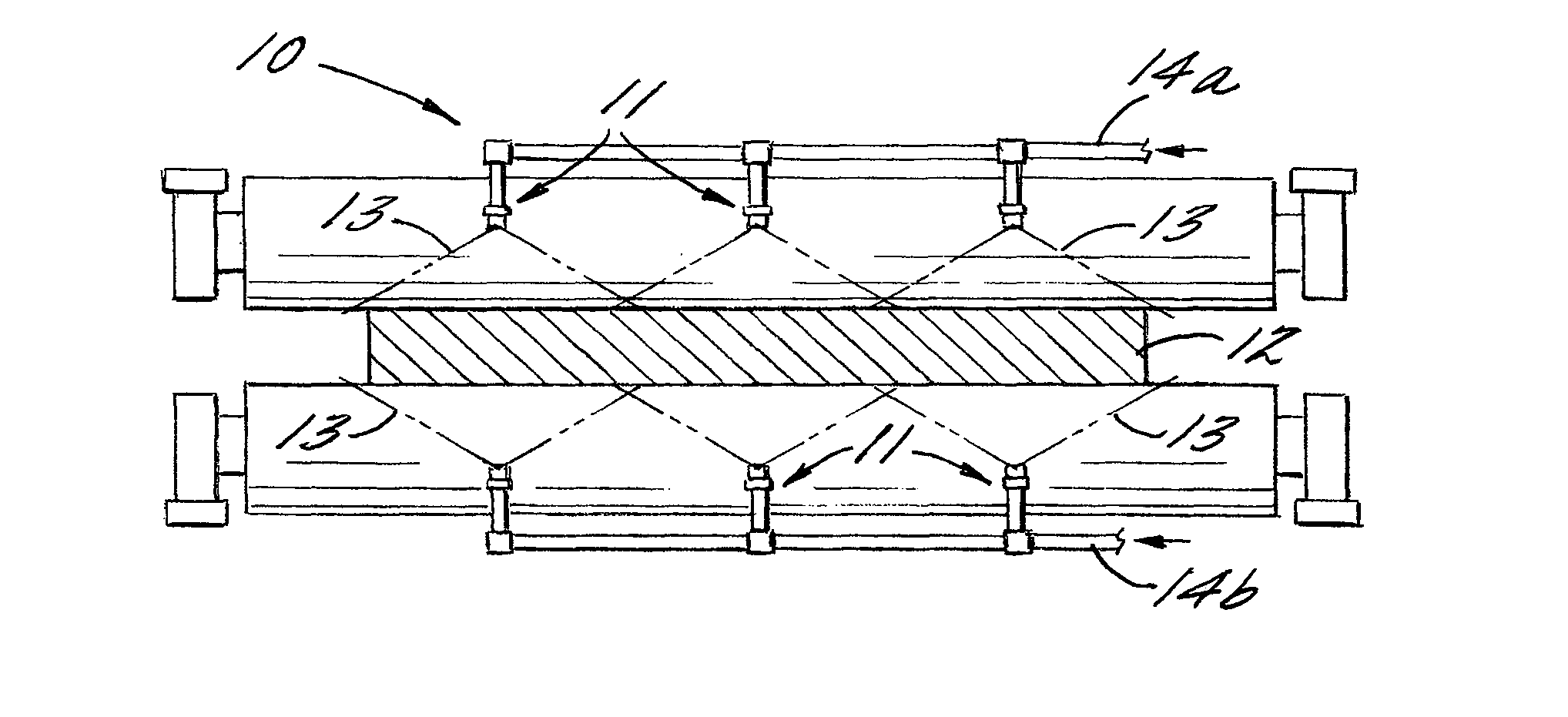
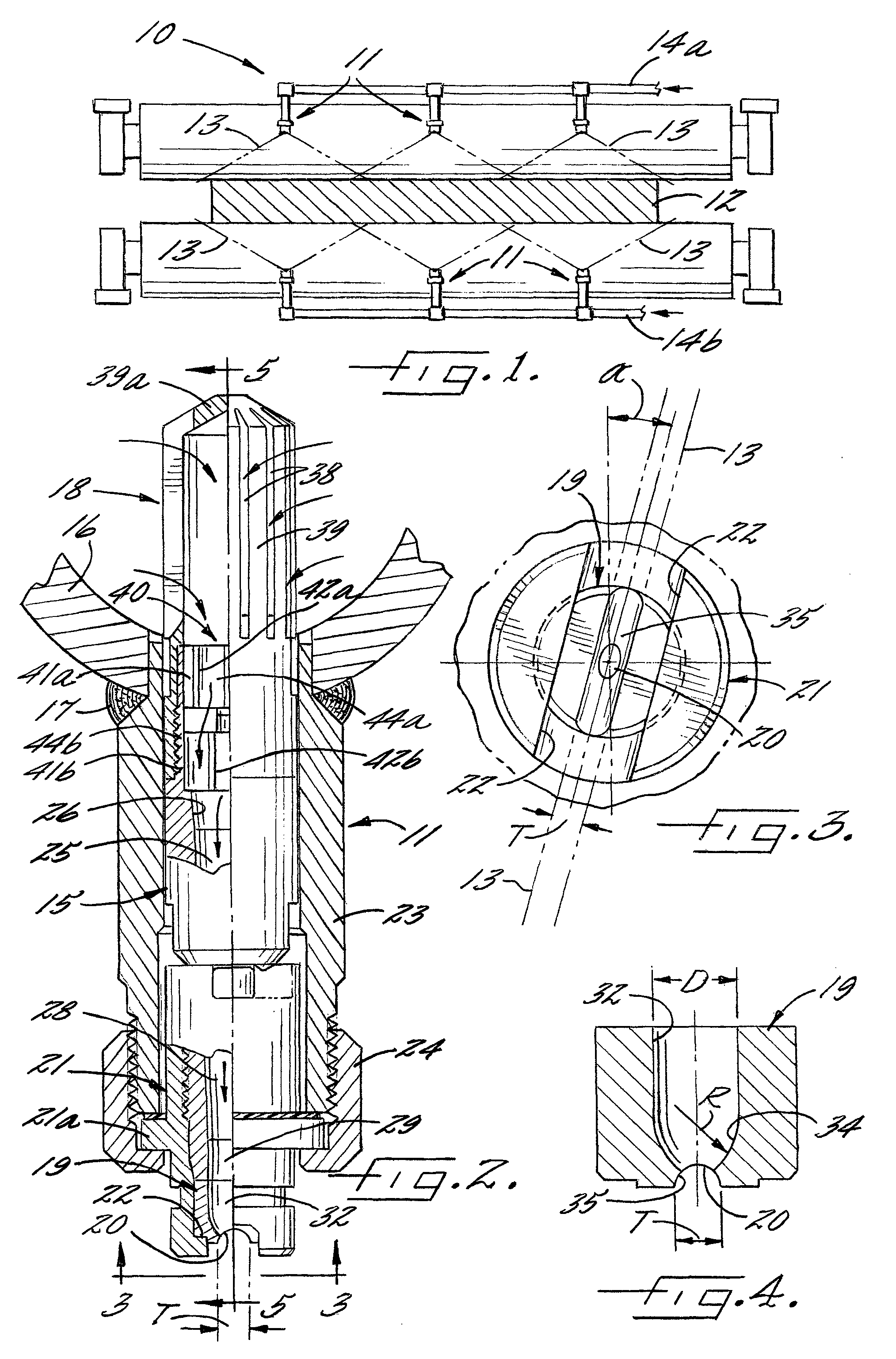
[0021]Referring now more particularly to the drawings, there is shown an illustrative descaling spraying system 10 having a plurality of spray nozzle assemblies 11 in accordance with the invention for directing a high pressure liquid spray on opposed sides of a moving steel slab 12 in a steel manufacturing operation. The spraying system 10 in this case comprises upper and lower liquid supply headers 14a, 14b, typically supplied with mill water that is recycled in the steel manufacturing facility. These spray nozzle assemblies 11 are mounted in laterally-spaced relation along the respective header 14a, 14b such that a plurality of flat, thin-line spray patterns 13 penetrate and remove scale across the entire width of the steel slab 12. Spray nozzle assemblies 11 in this case are supported in depending fashion from the upper liquid supply header 14a for directing liquid spray onto an upper side of the moving slab 12 and the spray nozzle assemblies 11 are supported in upwardly extendin...


PUM

PropertyMeasurementUnit
gap distanceaaaaaaaaaa
axial lengthaaaaaaaaaa
diameteraaaaaaaaaa

Abstract

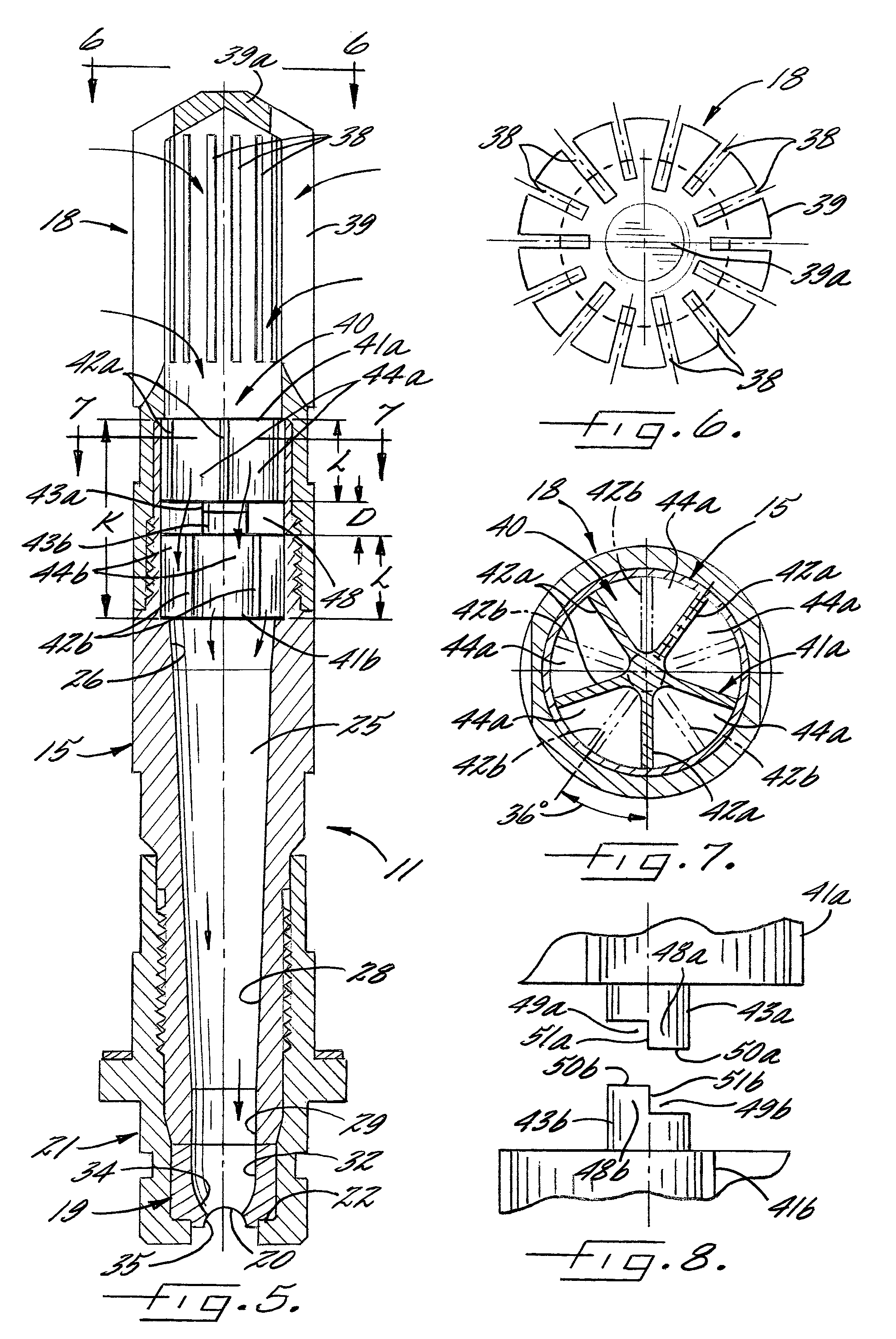
A spray nozzle assembly for directing thin, straight line, high pressure liquid spray onto moving steel slabs for penetrating and removing scale buildup in steel processing operations. The spray nozzle assembly includes a high impact attachment tube for accelerating liquid flow, a tungsten carbide spray tip at a discharge end of the high impact attachment tube for directing a flat spray pattern, an inlet defined by a strainer at an upstream end of the high impact attachment tube, and a staged vane section intermediate the inlet and spray tip for reducing liquid turbulence in the flow passageway. The vane section comprises a pair of axially spaced vanes each having a plurality of radial vane elements that define a plurality of laminar flow passageways, with the laminar flow passageways of one vane being circumferentially offset to the laminar flow passageways of the other vane.

Description

FIELD OF THE INVENTION[0001]The present invention relates generally to spray nozzle assemblies, and more particularly, to descaling spray nozzle assemblies operable for directing a wide thin-line high-pressure liquid discharge for penetrating and removing scale from steel in steel manufacturing operations.BACKGROUND OF THE INVENTION[0002]Descaling spray nozzle assemblies are extensively used in steel processing for directing a wide thin line high pressure spray onto the surface of steel slabs for penetrating and removing iron oxide scale buildup on the surfaces prior to rolling and subsequent processing of the steel. In such spraying systems, it is desirable that the high pressure liquid discharge be as thin as possible for effecting maximum impact pressure and penetration of the scale. It also is desirable that the distribution of the liquid discharge be uniform across the width of the spray pattern. Heretofore, the liquid distribution often is unevenly reduced toward the opposed e...

Claims


Application Information

Patent Timeline
Patent Type & Authority Patents(United States)
IPC IPC(8): B05B1/14B05B1/04B05B1/00
CPCB05B1/042B05B1/34B05B15/008B21B45/08B05B15/40B05B1/3402B05B1/04
Inventor KIOI, YOSHIYUKI
Owner SPRAYING SYST
Learn More