Magnetic field detecting element having thin stack with a plurality of free layers and thick bias magnetic layer

a magnetic layer and detector element technology, applied in the field of magnetic field detecting elements, can solve the problems of large limitation that originates from the layer configuration of the conventional cpp elements, restricts the reduction of the thickness of the spin-valve film, and limits the magnetization of the pinned layer as a whole, so as to achieve sufficient bias magnetic field and reduce the gap between the shields

Active Publication Date: 2011-03-29
TDK CORPARATION
View PDF13 Cites 4 Cited by
  • Summary
  • Abstract
  • Description
  • Claims
  • Application Information

AI Technical Summary

Benefits of technology

[0009]The present invention is directed to a CPP type magnetic field detecting element having a layer configuration that includes a stack with more than one free layers and that has a bias magnetic layer on the back side of the stack when viewed from the air bearing surface. One object of the present invention is to provide a magnetic field detecting element having the above-mentioned layer configuration that is capable of applying a sufficient bias magnetic field to the free layers, and of reducing the gap between the shields. Another object of the present invention is to provide a method of manufacturing such a magnetic field detecting element.
[0011]In accordance with this structure, the need for providing an antiferromagnetic layer and a synthetic pinned layer in the stack is obviated, and a reduction in the stack thickness is facilitated. On the other hand, the thickness of the bias magnetic layer can be set, independently of the stack thickness, to a thickness that is necessary for applying a required bias magnetic field. As a result, the thickness of the bias magnetic layer becomes larger than the stack thickness, and a stepped portion may be formed between the bias magnetic layer and the stack. However, since the auxiliary shielding layer is formed at the stepped portion, the magnetic field emitted from the adjacent bit on the same track of a recording medium can be effectively shielded. In this way, it is possible to apply a sufficient bias magnetic field to the free layers while reducing the gap between the shields, and thereby to provide a magnetic field detecting element which is easy to cope with high track recording density.

Problems solved by technology

However, there is large limitation that originates from the layer configuration in the conventional CPP elements.
Since the magnetization directions of the inner pinned layer and the outer pinned layer are anti-parallel to each other, magnetization of the pinned layer is limited as a whole.
This imposes limitation on a reduction in the thickness of the spin-valve film.
However, such a stack using two free layers has the problem described below.
Next, since the bias magnetic layer is provided facing only one surface of the stack, which is different from the conventional art, the magnetic field itself is apt to be dispersed, and efficient application of a magnetic field to the free layer is difficult.
For these reasons, it is difficult to ensure a magnetic field intensity of the bias magnetic layer that is necessary for magnetizing the free layers into a single magnetic domain.
However, if the stack thickness is determined in a manner that it corresponds to the thickness of the bias magnetic layer, a large decrease in the gap between the shields cannot be expected.

Method used


Image

  • Magnetic field detecting element having thin stack with a plurality of free layers and thick bias magnetic layer
  • Magnetic field detecting element having thin stack with a plurality of free layers and thick bias magnetic layer
  • Magnetic field detecting element having thin stack with a plurality of free layers and thick bias magnetic layer

Examples


Embodiment Construction

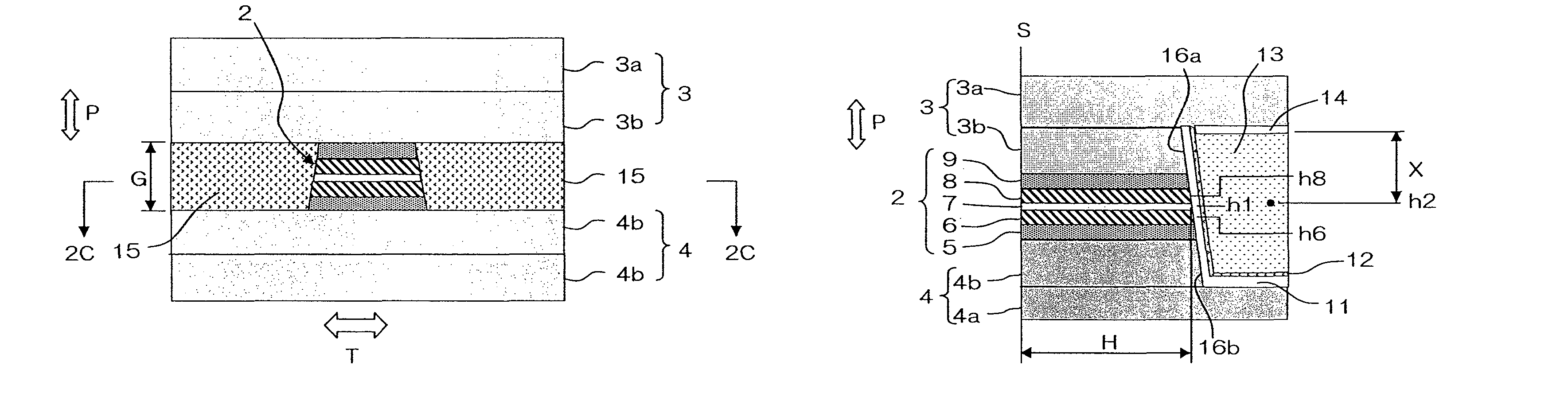
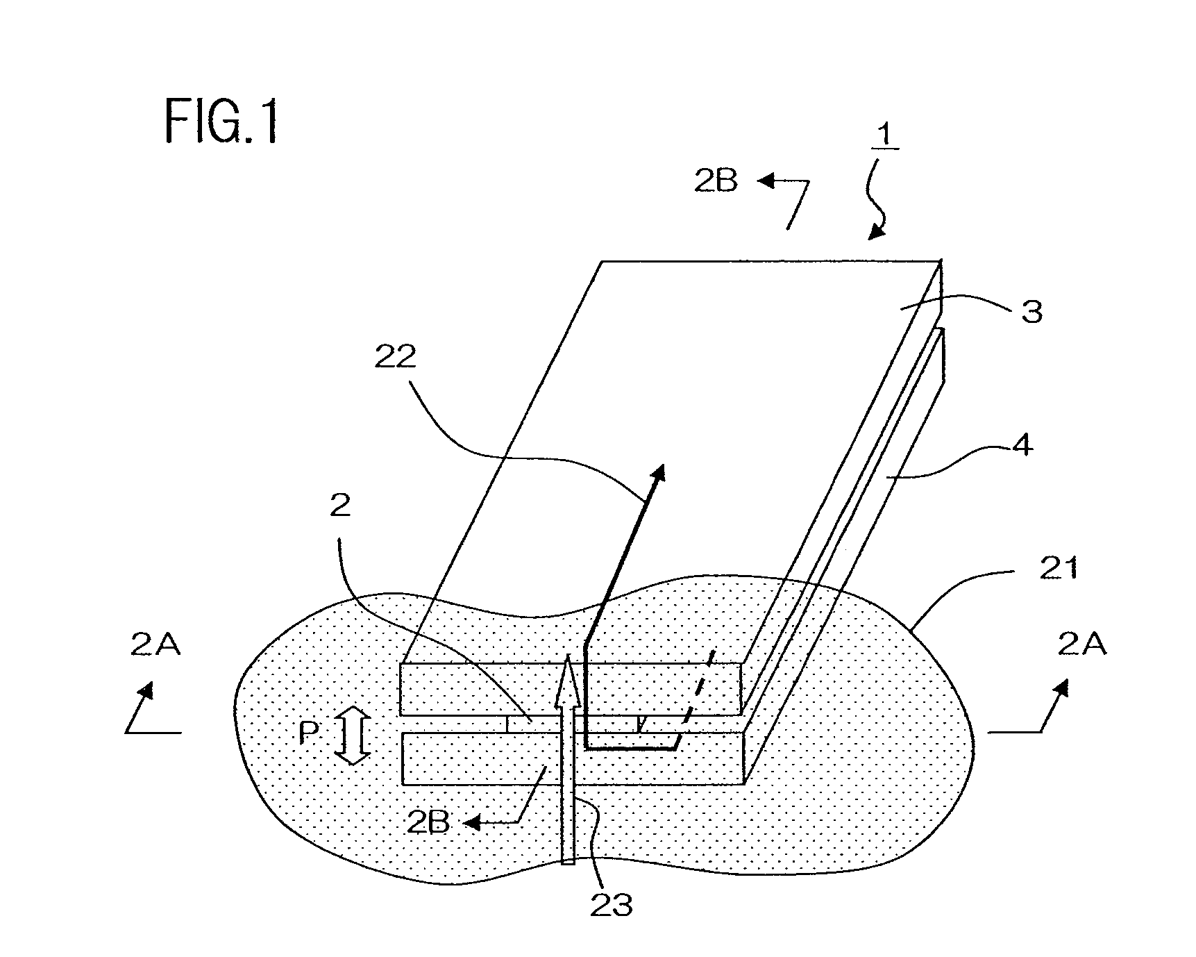
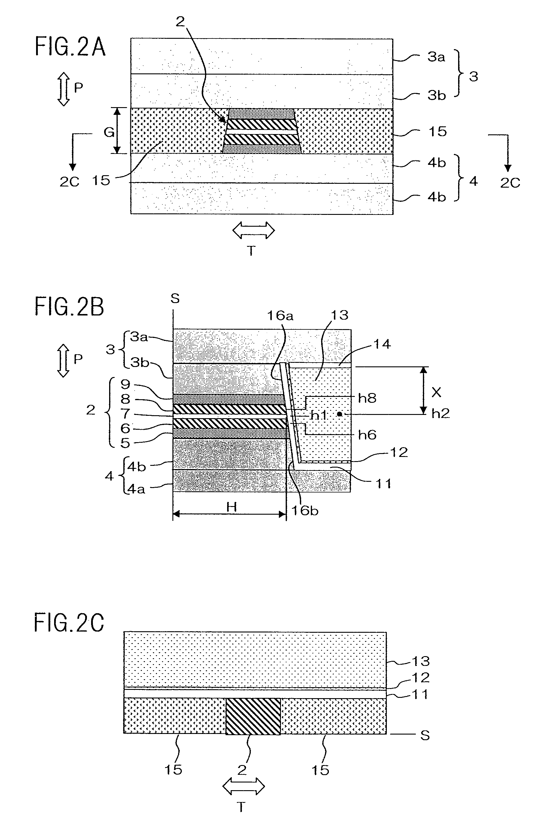
[0030]An embodiment of the present invention will now be described with reference to the attached drawings. A magnetic field detecting element of the present embodiment is particularly suitable for use as a read head portion of a thin film magnetic head of a hard disc drive. FIG. 1 is a conceptual perspective view of a magnetic field detecting element of the present embodiment. FIG. 2A is a side view of the magnetic field detecting element when viewed from 2A-2A direction of FIG. 1, i.e., viewed from the air bearing surface. FIG. 2B is a cross sectional view of the magnetic field detecting element taken along 2B-2B line of FIG. 1. FIG. 2C is a cross sectional view of the magnetic field detecting element taken along 2C-2C line of FIG. 2A. The air bearing surface refers to the surface of magnetic field detecting element 1 that faces recording medium 21.

[0031]Magnetic field detecting element 1 includes stack 2, upper shield electrode layer 3 and lower shield electrode layer 4 which are...


PUM

PropertyMeasurementUnit
thicknessaaaaaaaaaa
thicknessaaaaaaaaaa
thicknessaaaaaaaaaa

Abstract

A magnetic field detecting element comprising: a stack including an upper and magnetic layer, a lower magnetic layer, and a non-magnetic intermediate layer sandwiched therebetween, an upper and lower shield electrode layer provided in a manner that they sandwich said stack therebetween in a direction of stacking of the stack, wherein the upper and lower shield electrode layer supply sense current in the direction of stacking and magnetically shield the stack; a bias magnetic layer provided on a surface of the stack, the surface being opposite to an air bearing surface of said stack, and insulating films provided on both sides of the stack with regard to a track width direction thereof. The bias magnetic layer has a larger thickness than the stack, and the upper shield electrode layer and / or said lower shield electrode layer includes an auxiliary shield layer which fills a stepped portion formed by the stack and bias magnetic layer.

Description

BACKGROUND OF THE INVENTION[0001]1. Field of the Invention[0002]The present invention relates to a magnetic field detecting element and a manufacturing method thereof, and more particularly, to the structure of a magnetic field detecting element having a plurality of free layers.[0003]2. Description of the Related Art[0004]As a reproduction element of a thin film magnetic head, GMR (Giant Magneto Resistance) elements are known. Hitherto, CIP (Current In Plane)-GMR element, in which sense current flows in a direction that is horizontal to the film surface of the element, have been mainly used. In recent years, however, in order to cope with higher density recording, elements have been developed in which sense current flows in a direction that is perpendicular to the film surface of the element. TMR elements utilizing the TMR (Tunnel Magneto-Resistance) effect, and CPP (Current Perpendicular to the Plane) elements utilizing the GMR effect are known as the elements of this type. In par...

Claims


Application Information

Patent Timeline
Patent Type & Authority Patents(United States)
IPC IPC(8): G11B5/39
CPCB82Y25/00G01R33/093G11B5/3912G11B5/3932G11B5/398H01L43/08H01L43/12H10N50/10H10N50/01
Inventor MIYAUCHI, DAISUKEMACHITA, TAKAHIKO
Owner TDK CORPARATION
Why Eureka
Try Eureka