Magnetoresistive effect thin-film magnetic head with anti-ferromagnetic layer for magnetic domain control

a thin-film magnetic head and anti-ferromagnetic layer technology, applied in the field of thin-film magnetic heads, can solve the problem of not being able to apply to the free layer of the multi-layered structure a sufficient bias magnetic field for magnetic domain control, and achieve the effect of good linear response and no nois

Active Publication Date: 2010-04-06
TDK CORPARATION
View PDF6 Cites 2 Cited by
  • Summary
  • Abstract
  • Description
  • Claims
  • Application Information

AI Technical Summary

Benefits of technology

[0011]It is therefore an object of the present invention to provide a thin-film magnetic head with an MR element capable of supplying to a magnetization-free layer of an MR multi-layered structure a sufficient bias magnetic field for magnetic domain control, resulting in a good linear response with no noise, to provide a magnetic disk drive apparatus provided with the thin-film magnetic head, and to provide a manufacturing method of the thin-film magnetic head.
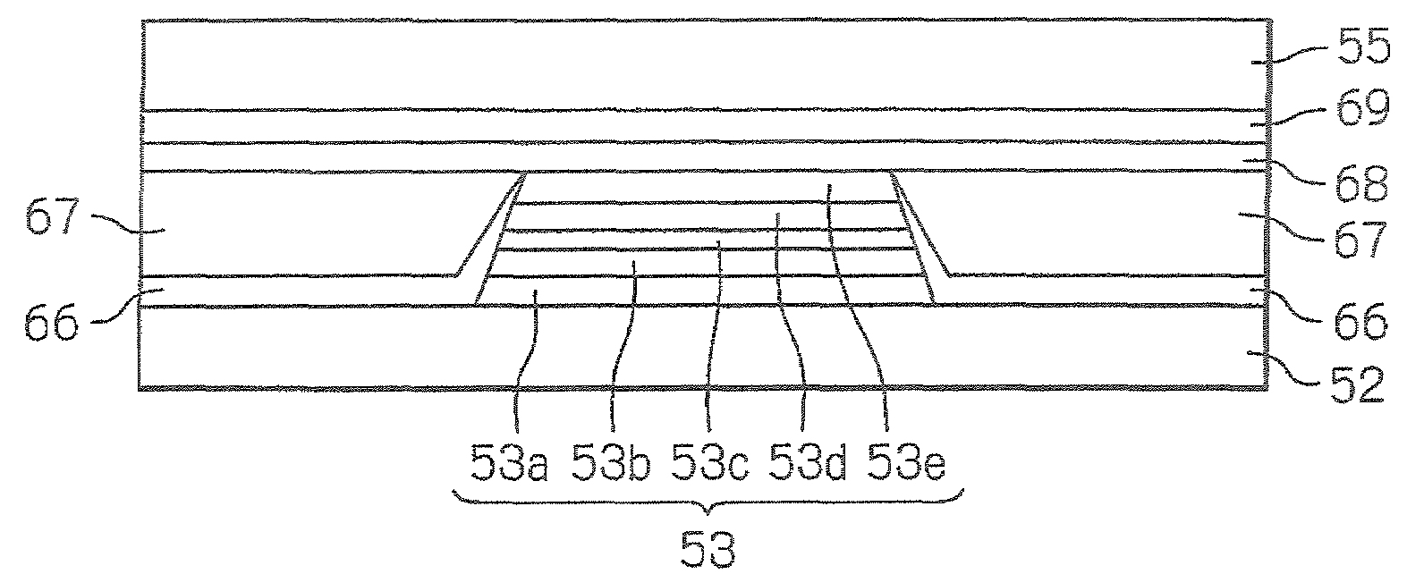
[0013]The anti-ferromagnetic layer for magnetic domain control mutually exchange-coupled to the soft magnetic layers for magnetic domain control continuously covers over the MR multi-layered structure and the soft magnetic layers for magnetic domain control. Thus, it is possible to make the thickness of the anti-ferromagnetic layer for magnetic domain control sufficiently large in the vicinity of a junction of the MR multi-layered structure. Thereby, the exchange-coupling between the anti-ferromagnetic layer for magnetic domain control and the soft magnetic layers for magnetic domain control is made sufficiently so strong that in this portion, it becomes possible to supply to the magnetization-free layer of the MR multi-layered structure sufficient bias magnetic fields for magnetic domain control. As a result, the magnetization-free layer can be controlled to have a single magnetic domain with reliability, and as a result, noise such as Barkhausen noise can be suppressed to achieve better linear response characteristics of the MR read head element.
[0019]After the lift-off for forming the insulation layer and the soft magnetic layers for magnetic domain control, the anti-ferromagnetic layer for magnetic domain control is stacked on the MR multi-layered structure and the soft magnetic layers for magnetic domain control. Therefore, the anti-ferromagnetic layer for magnetic domain control continuously covers over the MR multi-layered structure and the soft magnetic layers for magnetic domain control. Thus, it is possible to make the thickness of the anti-ferromagnetic layer for magnetic domain control sufficiently large in the vicinity of a junction of the MR multi-layered structure. Thereby, the exchange-coupling between the anti-ferromagnetic layer for magnetic domain control and the soft magnetic layers for magnetic domain control is made sufficiently so strong that in this portion, it becomes possible to supply to the magnetization-free layer of the MR multi-layered structure sufficient bias magnetic fields for magnetic domain control. As a result, the magnetization-free layer can be controlled to have a single magnetic domain with reliability, and as a result, noise such as Barkhausen noise can be suppressed to achieve better linear response characteristics of the MR read head element.

Problems solved by technology

This makes it impossible to apply to the free layer of the MR multi-layered structure a sufficient bias magnetic field for magnetic domain control.

Method used


Image

  • Magnetoresistive effect thin-film magnetic head with anti-ferromagnetic layer for magnetic domain control
  • Magnetoresistive effect thin-film magnetic head with anti-ferromagnetic layer for magnetic domain control
  • Magnetoresistive effect thin-film magnetic head with anti-ferromagnetic layer for magnetic domain control

Examples


Embodiment Construction

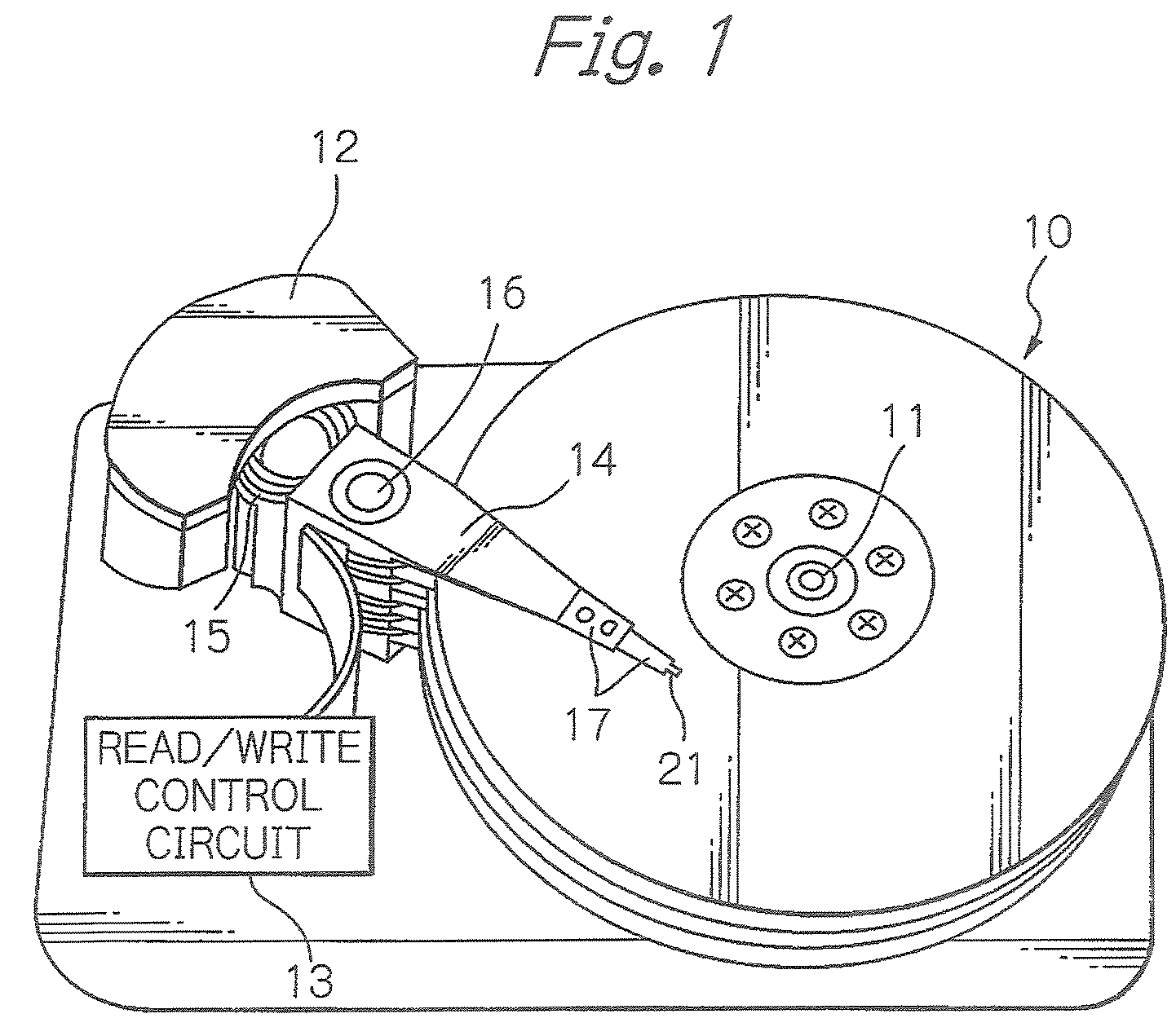
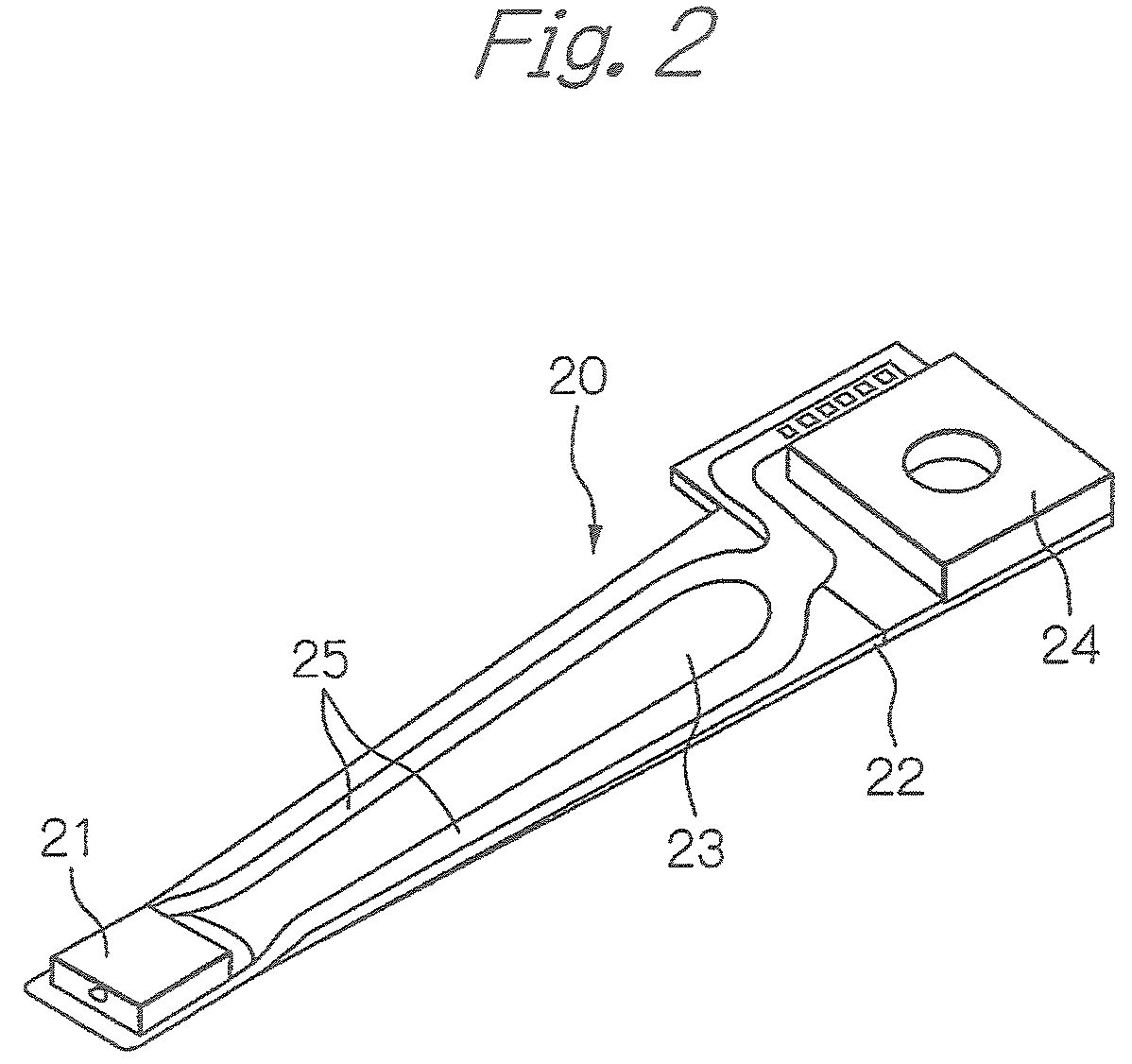
[0039]FIG. 1 schematically illustrates a configuration of main parts of a magnetic disk drive apparatus, as a preferred embodiment of the present invention, FIG. 2 illustrates one configuration example of an HGA shown in FIG. 1, FIG. 3 illustrates a composite thin-film magnetic head attached to the distal end section of the HGA shown in FIG. 2, and FIG. 4 illustrates a magnetic head element portion of the composite thin-film magnetic head shown in FIG. 3, seen from an element formation surface side of a slider substrate.

[0040]In FIG. 1, reference numeral 10 denotes a plurality of magnetic hard disks rotating in operation around the rotation shaft of a spindle motor 11, 12 denotes an assembly carriage device for positioning each composite thin-film magnetic head or magnetic head slider on a track of each disk, and 13 denotes a read / write control circuit for controlling read and write operations of the thin-film magnetic head, respectively.

[0041]The assembly carriage device 12 has a p...


PUM

PropertyMeasurementUnit
thicknessaaaaaaaaaa
thicknessaaaaaaaaaa
thicknessaaaaaaaaaa

Abstract

A thin-film magnetic head includes a lower electrode layer, an MR multi-layered structure, through which a current passes in a direction perpendicular to a lamination plane, stacked on the lower electrode layer, soft magnetic layers for magnetic domain control formed on both sides in a track width direction of the MR multi-layered structure, an anti-ferromagnetic layer for magnetic domain control continuously stacked on the MR multi-layered structure and the soft magnetic layers for magnetic domain control, the anti-ferromagnetic layer mutually exchanged-coupled to the soft magnetic layers for magnetic domain control, and an upper electrode layer stacked on the anti-ferromagnetic layer for magnetic domain control.

Description

BACKGROUND OF THE INVENTION[0001]1. Field of the Invention[0002]The present invention relates to a thin-film magnetic head with a magnetoresistive effect (MR) read head element for reading out a magnetic intensity in a magnetic recording medium or the like and outputting it as a signal, to a magnetic disk drive apparatus provided with the thin-film magnetic head, and to a manufacturing method of the thin-film magnetic head.[0003]2. Description of the Related Art[0004]In order to satisfy the demand for higher recording density and downsizing in a hard disk drive (HDD) apparatus, higher sensitivity and larger output of a thin-film magnetic head are required. In accordance with the requirement, the performance improvement on a giant magnetoresistive effect (GMR) head with a GMR read head element has progressed. At the same time, a practical application of a tunnel magnetoresistive effect (TMR) head with a TMR read head element, in which the resistance change ratio is expected to more t...

Claims


Application Information

Patent Timeline
Patent Type & Authority Patents(United States)
IPC IPC(8): G11B5/39
CPCB82Y10/00B82Y25/00G11B5/3932G11B5/3909G11B5/1278G11B2005/3996G11B5/3967
Inventor KAGAMI, TAKEO
Owner TDK CORPARATION
Why Eureka
Try Eureka