Magnetoresistive effect thin-film magnetic head with Anti-ferromagnetic layer for magnetic domain control

a thin-film magnetic head and anti-ferromagnetic layer technology, applied in the field of thin-film magnetic heads, can solve the problem of not being able to apply to the free layer of the mr multi-layered structure a sufficient bias magnetic field for magnetic domain control, and achieve the effect of good linear response and no nois

Active Publication Date: 2008-06-19
TDK CORPARATION
View PDF4 Cites 4 Cited by
  • Summary
  • Abstract
  • Description
  • Claims
  • Application Information

AI Technical Summary

Benefits of technology

[0011]It is therefore an object of the present invention to provide a thin-film magnetic head with an MR element capable of supplying to a magnetization-free layer of an MR multi-layered structure a sufficient bias magnetic field for magnetic domain control, resulting in a good linear response with no noise, to provide a magnetic disk drive apparatus provided with the thin-film magnetic head, and to provide a manufacturing method of the thin-film magnetic head.

Problems solved by technology

This makes it impossible to apply to the free layer of the MR multi-layered structure a sufficient bias magnetic field for magnetic domain control.

Method used


Image

  • Magnetoresistive effect thin-film magnetic head with Anti-ferromagnetic layer for magnetic domain control
  • Magnetoresistive effect thin-film magnetic head with Anti-ferromagnetic layer for magnetic domain control
  • Magnetoresistive effect thin-film magnetic head with Anti-ferromagnetic layer for magnetic domain control

Examples


Embodiment Construction

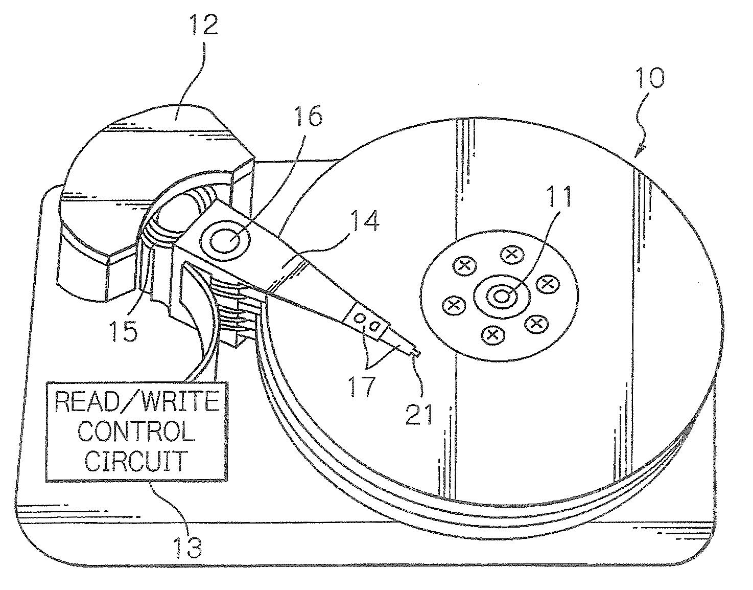
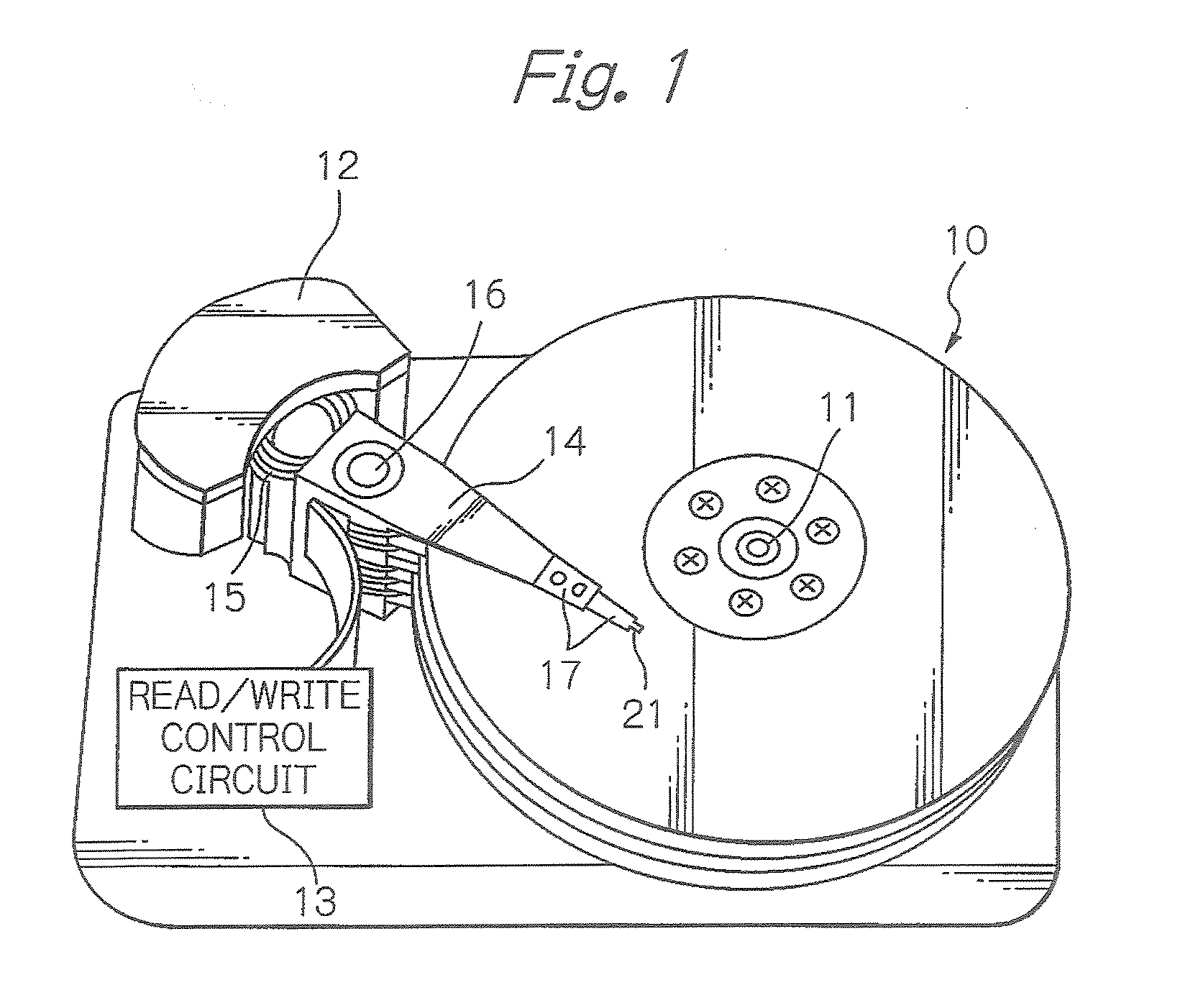
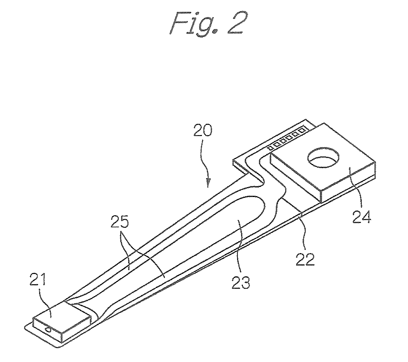
[0039]FIG. 1 schematically illustrates a configuration of main parts of a magnetic disk drive apparatus, as a preferred embodiment of the present invention, FIG. 2 illustrates one configuration example of an HGA shown in FIG. 1, FIG. 3 illustrates a composite thin-film magnetic head attached to the distal end section of the HGA shown in FIG. 2, and FIG. 4 illustrates a magnetic head element portion of the composite thin-film magnetic head shown in FIG. 3, seen from an element formation surface side of a slider substrate.

[0040]In FIG. 1, reference numeral 10 denotes a plurality of magnetic hard disks rotating in operation around the rotation shaft of a spindle motor 11, 12 denotes an assembly carriage device for positioning each composite thin-film magnetic head or magnetic head slider on a track of each disk, and 13 denotes a read / write control circuit for controlling read and write operations of the thin-film magnetic head, respectively.

[0041]The assembly carriage device 12 has a p...


PUM

PropertyMeasurementUnit
thicknessaaaaaaaaaa
thicknessaaaaaaaaaa
thicknessaaaaaaaaaa

Abstract

A thin-film magnetic head includes a lower electrode layer, an MR multi-layered structure, through which a current passes in a direction perpendicular to a lamination plane, stacked on the lower electrode layer, soft magnetic layers for magnetic domain control formed on both sides in a track width direction of the MR multi-layered structure, an anti-ferromagnetic layer for magnetic domain control continuously stacked on the MR multi-layered structure and the soft magnetic layers for magnetic domain control, the anti-ferromagnetic layer mutually exchanged-coupled to the soft magnetic layers for magnetic domain control, and an upper electrode layer stacked on the anti-ferromagnetic layer for magnetic domain control.

Description

BACKGROUND OF THE INVENTION[0001]1. Field of the Invention[0002]The present invention relates to a thin-film magnetic head with a magnetoresistive effect (MR) read head element for reading out a magnetic intensity in a magnetic recording medium or the like and outputting it as a signal, to a magnetic disk drive apparatus provided with the thin-film magnetic head, and to a manufacturing method of the thin-film magnetic head.[0003]2. Description of the Related Art[0004]In order to satisfy the demand for higher recording density and downsizing in a hard disk drive (HDD) apparatus, higher sensitivity and larger output of a thin-film magnetic head are required. In accordance with the requirement, the performance improvement on a giant magnetoresistive effect (GMR) head with a GMR read head element has progressed. At the same time, a practical application of a tunnel magnetoresistive effect (TMR) head with a TMR read head element, in which the resistance change ratio is expected to more t...

Claims


Application Information

Patent Timeline
Patent Type & Authority Applications(United States)
IPC IPC(8): G11B5/31
CPCB82Y10/00B82Y25/00G11B5/1278G11B2005/3996G11B5/3932G11B5/3967G11B5/3909
Inventor KAGAMI, TAKEO
Owner TDK CORPARATION
Why Eureka
Try Eureka