Linearization technique for current mode filters

a current mode filter and linearization technology, applied in pulse techniques, computer operations for integration/differentiation, instruments, etc., can solve the problems of active devices introducing distortion into the signal that travels through active devices, and achieve the effect of improving the linear respons

Inactive Publication Date: 2008-08-19
SEMICON COMPONENTS IND LLC
View PDF5 Cites 2 Cited by
  • Summary
  • Abstract
  • Description
  • Claims
  • Application Information

AI Technical Summary

Benefits of technology

[0027]The present invention also provides advantages of a smaller device size and lower power dissipation at a given low voltage and high frequency operation compared to known current mode circuitry.
[0029]The present invention improves the linear response by placing a linearizing element in series with the capacitor. In a preferred embodiment, a common source amplifier drives one side of the capacitor with a voltage gain that magnifies the capacitors apparent value, the Miller effect. The current through the common source amplifier is a mirror of the non-linear current element through the active device. This non-linear mirror current is applied through a resistor (a linear device) and placed in series with the capacitor to introduce a linear element to the voltage across the capacitor.

Problems solved by technology

Since the gm portion is non-linear with respect to the control voltage for the active device and that control voltage is across the capacitor, the active device introduces distortion into the signal that travels through the active device.

Method used


Image

  • Linearization technique for current mode filters
  • Linearization technique for current mode filters
  • Linearization technique for current mode filters

Examples


Embodiment Construction

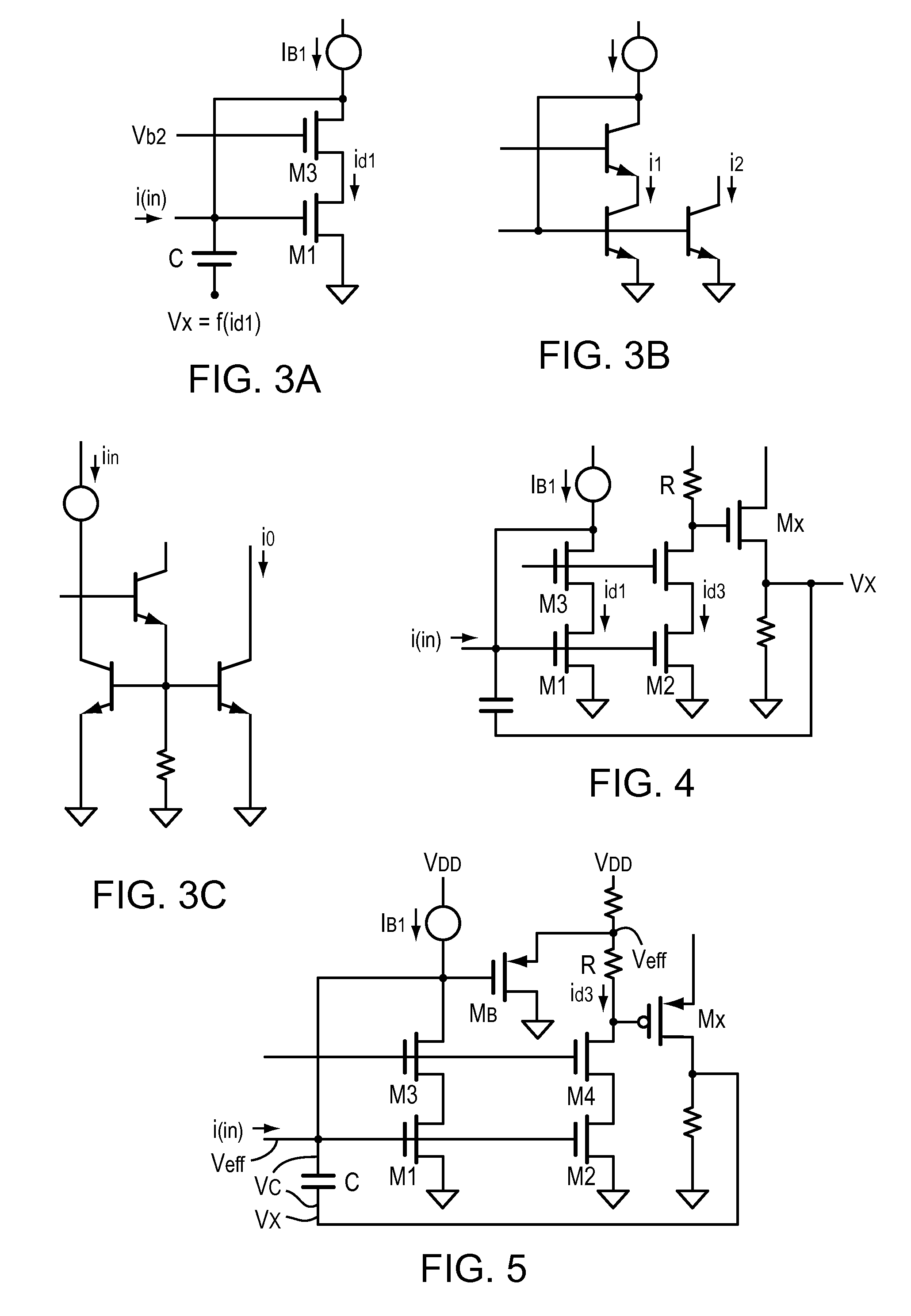
[0041]FIG. 3A is a simplified schematic of a preferred embodiment illustrating the present invention. Here, a voltage Vx is developed from id1 and applied to the end of the capacitor. The implementation is designed so that the voltage across the capacitor Vc=Veff−Vx, and circuit design that produces—Vx which acts to compensate for the non-linear terms found in Veff. FIG. 3B represents a diode connected bipolar cascade set of transistors and a current mirror, where i2 is a mirror of i1. In FIG. 3C the transistor T2 helps to reduce errors attributable to base currents, as is known to those skilled in the art. MOS circuits are used for the following discussion, but bipolar or hybrids thereof may be used to advantage.

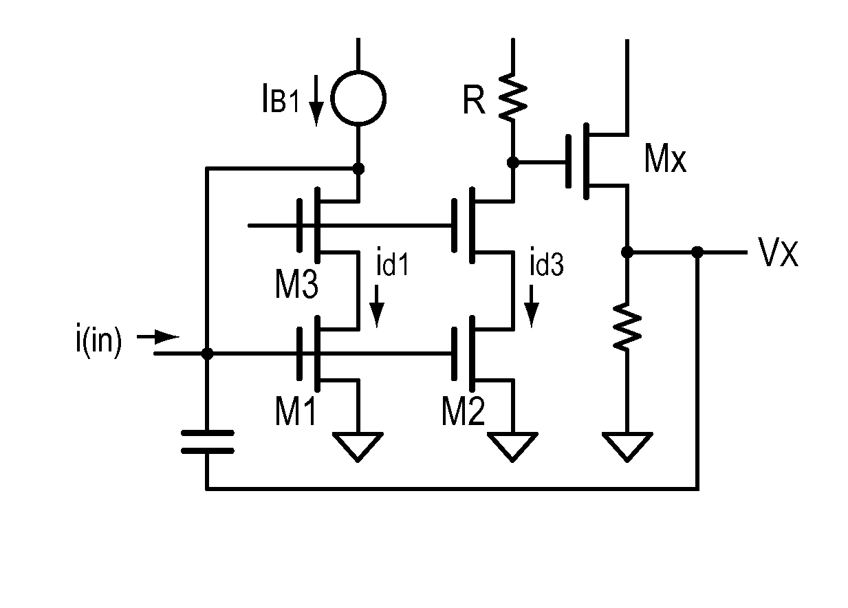
[0042]FIG. 4 is a preferred embodiment circuit to produce Vx. Here the current mirror is designed for id3=id1, and the voltage drop across R is the linear function (R)id1. The source follower Mx drives the linear signal Vx back to the capacitor C.

[0043]In this instance the ...


PUM


Abstract

A circuit is disclosed that compensates for the non-linearity of a current mode real pole producing circuit used to generate poles and zeros in complex filter circuits. The non-linearity of the prior art is compensated by driving one end of the primary pole producing capacitor with a signal derived from the drain current and fed back so as to counteract the non-linearity factors.

Description

BACKGROUND OF THE INVENTION[0001]1. Field of the Invention[0002]The present invention relates to current mode circuitry employed for creation of poles and zeros that are combined with feedback to create complex filter functions. More particularly, the present invention relates to a cell structure having a current mirror and a capacitor to create a single real pole with which virtually any filter function can be realized using scale factors, summers, feedback and feedforward circuits. The term “real” as used herein references the “real” axis in the complex plane.[0003]2. Background Information[0004]Current mode signal processing is common due to its advantages in low voltage applications and where high speed and / or small size are important compared to voltage mode circuitry. Diode connected devices exhibit such characteristics in current mirror configurations. Diode connected circuits also exhibit few internal nodes with parasitic poles thus increasing operating frequencies.[0005]Dio...

Claims


Application Information

Patent Timeline
Patent Type & Authority Patents(United States)
IPC IPC(8): H03K5/00
CPCH03F1/223H03F1/3205H03F1/342H03F2200/91H03F2200/453H03F2200/61H03F2200/75H03F2200/366
Inventor DEVOLK, BURTON
Owner SEMICON COMPONENTS IND LLC
Why Eureka
Try Eureka