Method and device for building of a network coding scheme for data transmission, corresponding computer program product and storage means

a network coding and data transmission technology, applied in the field can solve the problems of network coding techniques that are very recent and have not yet found commercial applications, gain in latency, and gain in network capacity, so as to reduce computation capacity and resources

Active Publication Date: 2011-03-29
CANON KK
View PDF27 Cites 8 Cited by
  • Summary
  • Abstract
  • Description
  • Claims
  • Application Information

AI Technical Summary

Benefits of technology

[0035]Thus, the number of source nodes of the second set (resultant of the intersection) is optimized (maximized) and the quality of the network coding built is improved (since it implies a sub-network comprising more source nodes).
[0048]This enables the use of a finite field for the coding, this finite field comprising a larger number of elements, and hence reduces the computation capacities and resources needed.

Problems solved by technology

Network coding techniques are very recent and have not yet found commercial application except for the “Avalanche” (registered mark) system proposed by Microsoft Corporation.
Indeed, in case of incorrect adaptation, instead of receiving information that is partially exploitable, certain nodes may receive only non-exploitable information.
The result of this is a gain in capacity of the network, and a gain in latency.
They may carry out trivial coding, that is they may take incoming data elements and retransmit them.
The problem therefore lies in testing the graph that represents the network to establish the number of disjointed paths.
However, this known solution has several drawbacks.
One drawback of this known solution is that, even if its authors assert that it can be easily extended, the algorithms presented do not take account of the case of a shared medium which obviously entails the existence of delays.
It is easy to prove that their method fails for a shared medium, especially in the computation of multicast capacity.
Another drawback of this known solution is that it does not account of the existence of multiple multicast sources.
Furthermore, and more generally, no known technique of network coding is proposed when the number of sources is strictly greater than h (multicast capacity of the network), i.e. when the condition of the above-mentioned theorem is not respected.

Method used


Image

  • Method and device for building of a network coding scheme for data transmission, corresponding computer program product and storage means
  • Method and device for building of a network coding scheme for data transmission, corresponding computer program product and storage means
  • Method and device for building of a network coding scheme for data transmission, corresponding computer program product and storage means

Examples


Embodiment Construction

[0087]In all the figures of the present document, the identical elements and steps are designated by a same numerical reference.

6.1 Method

[0088]Referring now to FIGS. 4a and 4b, we present a particular embodiment of the method according to the invention.

[0089]This method can be executed when the network is started up or as soon as there is a change in topology.

[0090]The step E1 is the step for capturing the topology of the network. The means used to know the topology of the network are described in paragraph 6.2.1 here below. From the topology, the process also extracts the source and destination nodes and stores them in two lists.

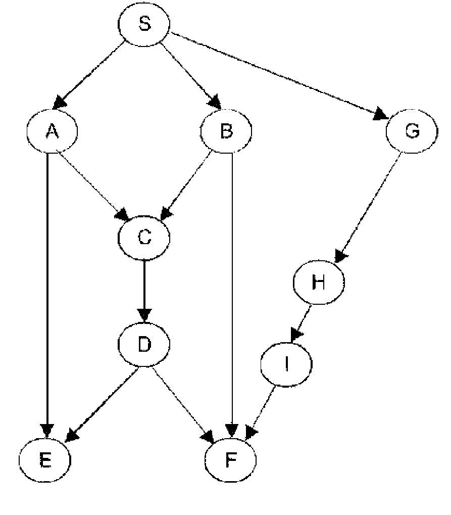
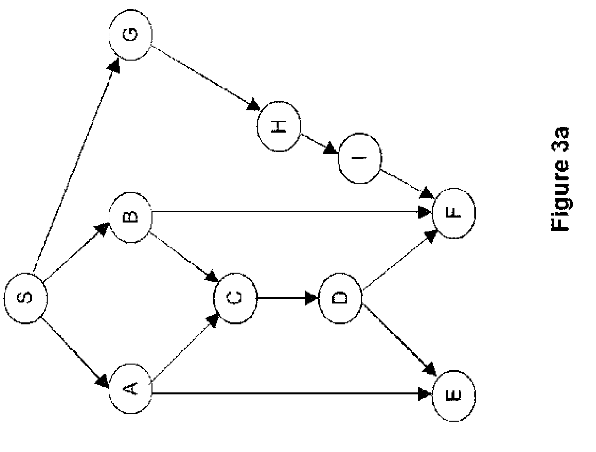
[0091]In the step E2, to create the graph, each node has an associated vertex of the graph. If the quality of reception from one node to another is sufficient, then an arc (directed edge) is created between the vertices representing them, the arc is directed towards the reception vertex.

[0092]It is possible to consider flows across a graph by designating a...


PUM


Abstract

A method provides for building a network coding scheme for the transmission of data between multiple source nodes and multiple destination nodes in a communications network having multiple nodes. The method includes the steps of: for each destination node, determining a first set of source nodes from which there exist disjointed paths, in the communications network, to reach the destination node; determining a second set of source nodes which is the intersection of the first determined sets for the destination nodes; and determining a sub-network for implementing the network coding. The sub-network includes source nodes which belong only to the second set of source nodes, the multiple destination nodes, and nodes included in the disjointed paths connecting the source nodes of the second set of source nodes and the destination nodes. The method also includes the step of building a network coding scheme based on the determined sub-network.

Description

1. FIELD OF THE INVENTION[0001]The field of the invention is that of the techniques of network coding (sometimes also called coding on network), i.e. techniques related to information theory and using codes that fulfill the information-transportation capacity of a network.[0002]More specifically, the invention relates to a technique for building a network coding system adapted to the transmission of data between a plurality of source nodes and a plurality of destination nodes in a communications network comprising a plurality of nodes.[0003]The invention can be applied especially but not exclusively in a shared-medium context. In such a context, the invention applies to information transport systems such as wireless networks in which all the members use a same frequency band accessed using a time-division multiplexing (TDM) or sets of computers sharing a common bus.[0004]Network coding techniques are very recent and have not yet found commercial application except for the “Avalanche...

Claims


Application Information

Patent Timeline
Patent Type & Authority Patents(United States)
IPC IPC(8): H04L12/28
CPCH04L45/04H04L45/128H04L45/14H04L45/22H04L45/28H04L47/10
Inventor LE BARS, PHILIPPESEVIN, JULIEN
Owner CANON KK
Why Eureka
Try Eureka