Multimode optical transmission device

a transmission device and optical transmission technology, applied in the field of multimode optical transmission devices, can solve the problems of difficult eavesdropping and inability to decod

Inactive Publication Date: 2011-03-29
PANASONIC CORP
View PDF34 Cites 0 Cited by
  • Summary
  • Abstract
  • Description
  • Claims
  • Application Information

AI Technical Summary

Benefits of technology

[0048]As described above, according to the present invention, at least one oscillation-mode light beam of multimode oscillation light is subjected to a predetermined operation to change a correlation relationship in optical intensity or optical phase between oscillation-mode light components. Thereby, an unpredictable noise component included as a physical property (natural phenomenon) in light occurs. When eavesdropping is performed, a signal-to-noise ratio of an optical signal received by an eavesdropper's optical receiving circuit is deteriorated due to the unpredictable noise component, so that an optical signal transmitted by the optical transmitting circuit cannot be correctly reproduced. Therefore, by utilizing the unpredictable noise component, an optical transmission device is provided which can achieve high-secrecy encrypted communication which cannot be analyzed or decrypted by computer processes.
[0049]Note that the terms “device” and “circuit” as used herein may mean a system or the like irrespective of the magnitude of the scale.

Problems solved by technology

Thereby, decoding is not possible for the third party other than authorized receivers having the “secret key”, i.e., it is significantly difficult to achieve eavesdropping, thereby making it possible to achieve data communication with a high level of secrecy.

Method used


Image

  • Multimode optical transmission device
  • Multimode optical transmission device
  • Multimode optical transmission device

Examples


first embodiment

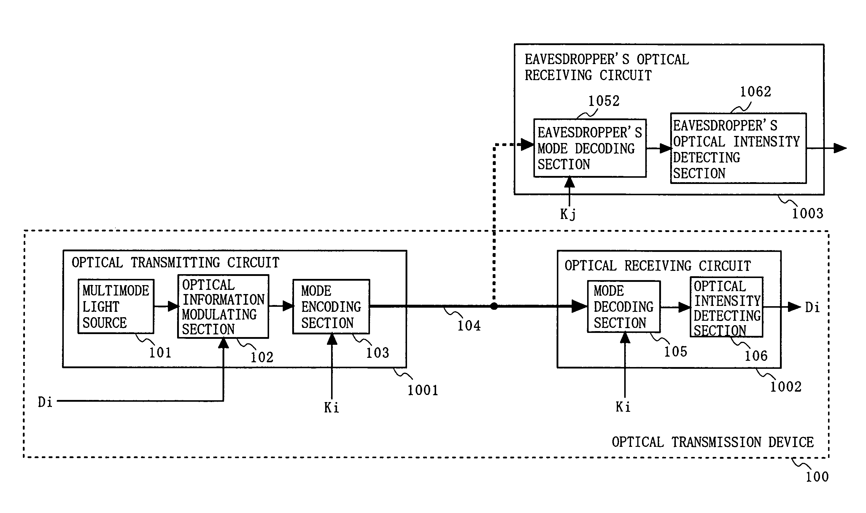
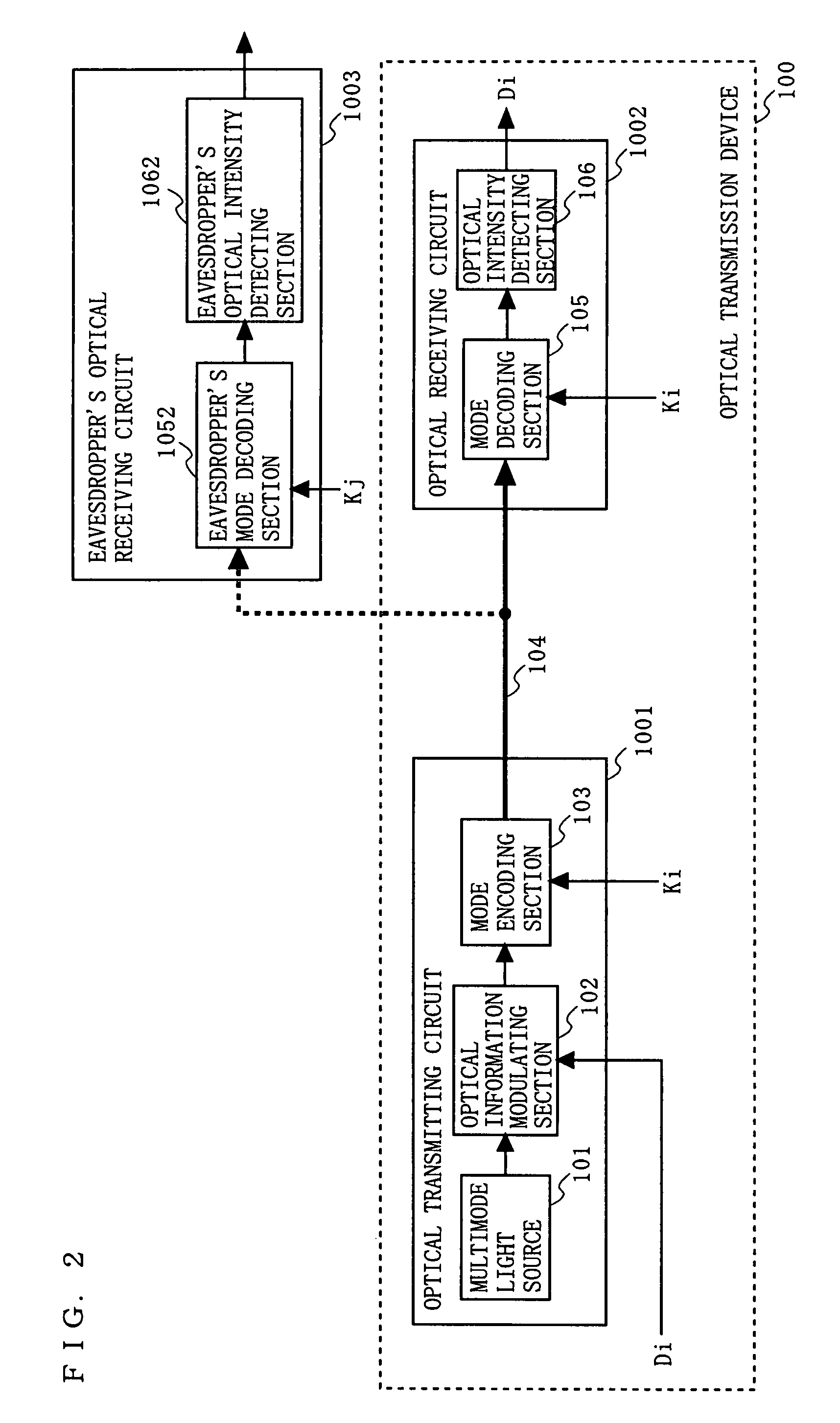
[0123]FIG. 2 is a diagram illustrating a configuration of an optical transmission device 100 supporting encrypted communication according to a first embodiment of the present invention. FIGS. 3A to 3E are schematic diagrams illustrating exemplary spectra of light (optical signals) in major parts of the optical transmission device 100. FIGS. 4A to 4E are schematic diagrams illustrating exemplary spectra of light (optical signals) in major parts of the optical transmission device 100 or an eavesdropper's optical receiving circuit 1003.

[0124]In FIG. 2, the optical transmission device 100 of this embodiment comprises a multimode light source 101, an optical information modulating section 102, a mode encoding section 103, an optical transmission channel 104, a mode decoding section 105, and an optical intensity detecting section 106. The multimode light source 101, the optical information modulating section 102, and the mode encoding section 103 constitute an optical transmitting circuit...

second embodiment

[0148]FIG. 7 is a diagram illustrating a configuration of an optical transmission device 200 supporting encrypted communication according to a second embodiment of the present invention. In FIG. 7, the optical transmission device 200 of this embodiment comprises a plurality of pairs of the optical transmitting circuit 1001 and the optical receiving circuit 1002 of FIG. 2 (two pairs in FIG. 7). The optical transmission device 200 comprises first and second multimode light sources 101, first and second optical information modulating sections 102, first and second mode encoding sections 103, an optical combining section 609, an optical transmission channel 104, an optical branching section 610, first and second mode decoding sections 105, and first and second optical intensity detecting sections 106. Note that the first (second) multimode light source 101, the first (second) optical information modulating section 102, and the first (second) mode encoding section 103 constitute the firs...

third embodiment

[0154]FIG. 8 is a diagram illustrating a configuration of an optical transmission device 200 supporting encrypted communication according to a third embodiment of the present invention. FIGS. 9A to 9C are schematic diagrams illustrating spectra of light (optical signals) in major parts of the optical transmission device 200 of FIG. 8.

[0155]In FIG. 8, the optical transmission device 200 of this embodiment comprises a multimode light source 201, an optical information modulating section 202, an optical separating section 203, a main optical transmission channel 204, a subsidiary optical transmission channel 205, and an optical intensity detecting section 206. The multimode light source 201, the optical information modulating section 202, and the optical separating section 203 constitute an optical transmitting circuit 2001. The optical intensity detecting section 206 constitutes an optical receiving circuit 2002. Note that, in FIG. 8, in order to describe an operation of this embodime...


PUM


Abstract

An optical transmitting circuit (2) modulates multimode oscillation light using an information signal, subjects at least one oscillation-mode light beam of the multimode oscillation light to a predetermined operation, and outputting the result to an optical transmission channel. An optical receiving circuit (8) receives an optical signal transmitted through the optical transmission channel, subjects the received optical signal to an operation reverse to the predetermined operation to recover an optical signal as it was before being subjected to the predetermined operation, and converting the recovered optical signal into an electrical signal, thereby reproducing the information signal.

Description

TECHNICAL FIELD[0001]The present invention relates to an optical transmission device for converting data into an optical signal, transmitting the optical signal, and receiving the transmitted optical signal. More particularly, the present invention relates to an optical transmission device which utilizes a noise component included as a physical property in light to significantly suppress interception / eavesdropping of data by the third party other than authorized receivers, thereby achieving encrypted data communication having a high level of secrecy.BACKGROUND ART[0002]FIG. 19 is a diagram illustrating a configuration of a conventional optical transmission device 91 supporting encrypted communication. In FIG. 19, the optical transmission device 91 comprises a light source 95, an optical information modulating section 94, an encryption section 93, an optical transmission channel 993, a decoding section 98, and an optical intensity detecting section 97. The light source 95, the optica...

Claims


Application Information

Patent Timeline
Patent Type & Authority Patents(United States)
IPC IPC(8): H04B10/12H04B10/2581H04B10/50
CPCH04B10/2581H04B10/502H04J14/005H04J14/02
Inventor FUSE, MASARU
Owner PANASONIC CORP
Why Eureka
Try Eureka