[0026] Although the measure of the present invention to increase the repetition interval at which the
signal is directed to the same areas of the sample up to reaching an optimum appears to be simple and in fact requires no high technical efforts in its application in
microscopy, the effects of the invention are surprisingly great. The yield of photons in methods of optically measuring a sample, in which a
fluorescence dye in the sample is subject to high light intensities in each repetition of a repeated
electromagnetic signal, may actually be increased tenfold. Particular examples for the beneficial application of the method are STED
microscopy as described in U.S. Pat. No. 7,253,893 B2 in which the de-excitation light has a particular
high intensity, and
fluorescence microscopy with multi-
photon excitation, in which very high light intensities have to be used, too. General advantages, however, also result in other methods of optically measuring a sample, like for example in lifetime imaging with pulsed light.
[0027] It is important to indicate that the electromagnetic signal, like for example a
light signal, may, within the scope of the present invention, comprise different components, like for example portions of different wavelengths or different parts following each other in time. By means of the invention, the repetition interval of the electromagnetic signal is determined, at which the electromagnetic signal is repeatedly directed at the sample for once optically measuring at least one measuring point.
[0028] The optimized repetition interval of the electromagnetic signal is at least 0.1 μs in the present invention. This corresponds to a maximum repetition rate at which the signal is directed at the same areas of the sample of 10 MHz. It is preferred, if the repetition interval of the electromagnetic signal is at least 1 μs. This corresponds to a repetition rate of less than 1 MHz. In determining the repetition rates corresponding to the repetition intervals, the duration of the respective electromagnetic signal has also to be considered, so that a slightly lower value than the reciprocal value of the repetition interval results for the repetition rate.
[0029] As already indicated, it makes no sense in the present invention to arbitrarily reduce the repetition frequency at which the electromagnetic signal is directed at any areas of the sample to optically measuring it. As a result, the duration of the optical measurement, within which a certain absolute yield of photons is achieved, would considerably be increased so that, for example, the
signal to noise ratio could strongly be deteriorated or stability problems could occur. Thus, it is preferred, if the repetition frequency of the electromagnetic signal is at least 100 kHz. A considerably lower repetition frequency could, however, be accepted, if the sample is simultaneously optically measured in a number n of measuring point, as the yield of photons per time is then increased by a factor n. Correspondingly, the repetition frequency of the signal may be reduced down to 100 kHz / n. If the sample is, for example, covered all over by the electromagnetic signal and observed by a camera, the number of the pixels of the camera may be regarded as n, so that n may even be quite high. By means of a reduction of the repetition frequency proportional to 1 / n, however, no relevant advantages with regards to the maximum yield of photons from the substance in the sample up to its bleaching are obtained, at least with higher values of n. These advantages occur already with an increase of the repetition interval of the electromagnetic signal up to about 0.1 μs to 10 μs depending on the particular substance.
[0030] For actually applying the present invention, a repetition frequency of the optical signal which is directed at the sample may be tuned downwards to increase the repetition interval. Such a repetition frequency usually is in the
order of magnitude of 80 MHz with most present optical methods in which an optical signal is repeatedly directed at a sample. For carrying out the invention, this repetition frequency is, for example, lowered down to 500 kHz.
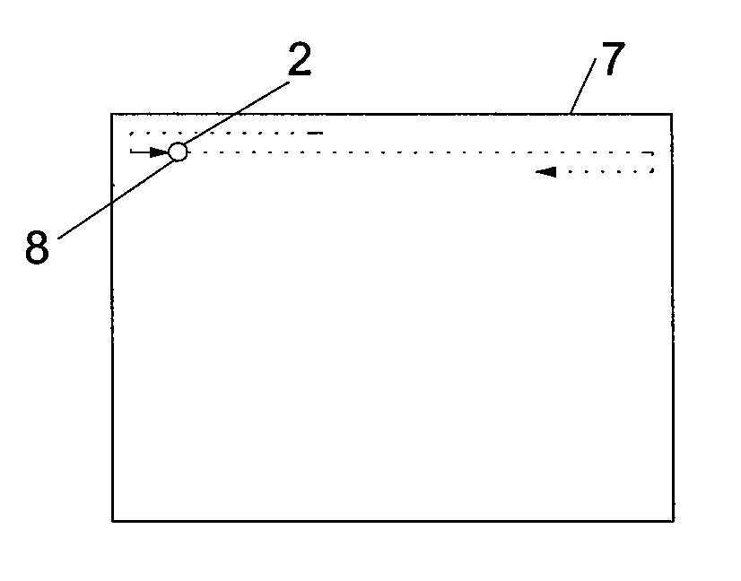
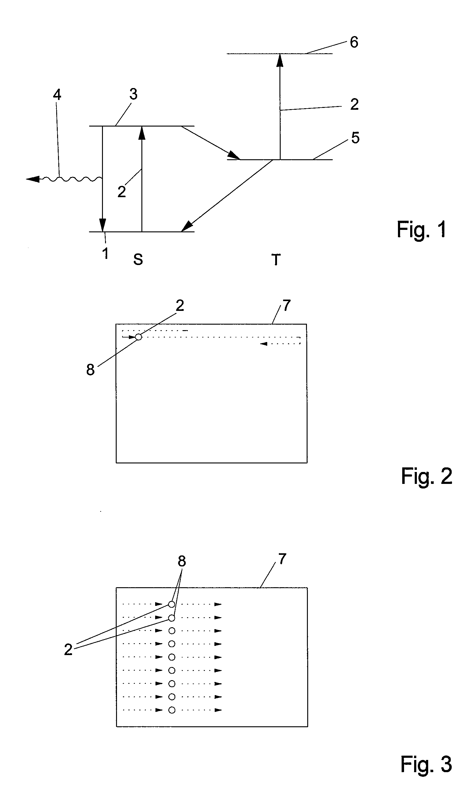
[0031] If the electromagnetic signal is at any one time only directed at a spatially limited area of the sample, and if the sample is scanned with the electromagnetic signal or the spatially limited area, a scanning velocity at which the sample is spatially scanned may also be increased instead of reducing the repetition frequency of the electromagnetic signal to increase the repetition interval in time. Both measures, i.e. the reduction of the repetition frequency and the increase of the scanning velocity may also be used simultaneously to raise the repetition interval to a value according to the invention. It is important that the repetition interval at which the same area of the sample is repeatedly subjected to the electromagnetic signal stays above the minimum according to the present invention. Scanning the sample with the electromagnetic signal at such a
high velocity that two consecutive repetitions of the electromagnetic signal do not cover the same area of the sample so that the areas subjected to the optical signal at any one time do not overlap contributes to this end. In this case, the repetition interval at which the electromagnetic signal is directed at the sample may become very high without a decrease in the yield of photons per time unit.

