High frequency power amplifier, high frequency front-end circuit, and radio communication device

Active Publication Date: 2016-07-21
MURATA MFG CO LTD
View PDF3 Cites 0 Cited by
  • Summary
  • Abstract
  • Description
  • Claims
  • Application Information

AI Technical Summary

Benefits of technology

The patent is about a power amplifier that can amplify a transmission signal to a desired level while reducing the output level of a reception frequency component of the signal. This improves the signal to noise ratio of the reception signal.

Problems solved by technology

The high frequency front-end circuits have the problem of wraparound of the transmission signal to the receiver side circuit.
More specifically, the transmission signal outputted from the power amplifier sometimes wraps around the receiver side circuit, thus deteriorating a signal to noise ratio of the reception signal.
Also, in the multimode / multiband power amplifier, although a high gain is obtained in the wide band, a gain of a certain degree is undesirably obtained in a frequency band other than the desired band.
Thus, the reception frequency component of the transmission signal is amplified by the power amplifier and wraps around the receiver side circuit, thus further deteriorating the signal to noise ratio of the reception signal.

Method used


Image

  • High frequency power amplifier, high frequency front-end circuit, and radio communication device
  • High frequency power amplifier, high frequency front-end circuit, and radio communication device
  • High frequency power amplifier, high frequency front-end circuit, and radio communication device

Examples


first embodiment

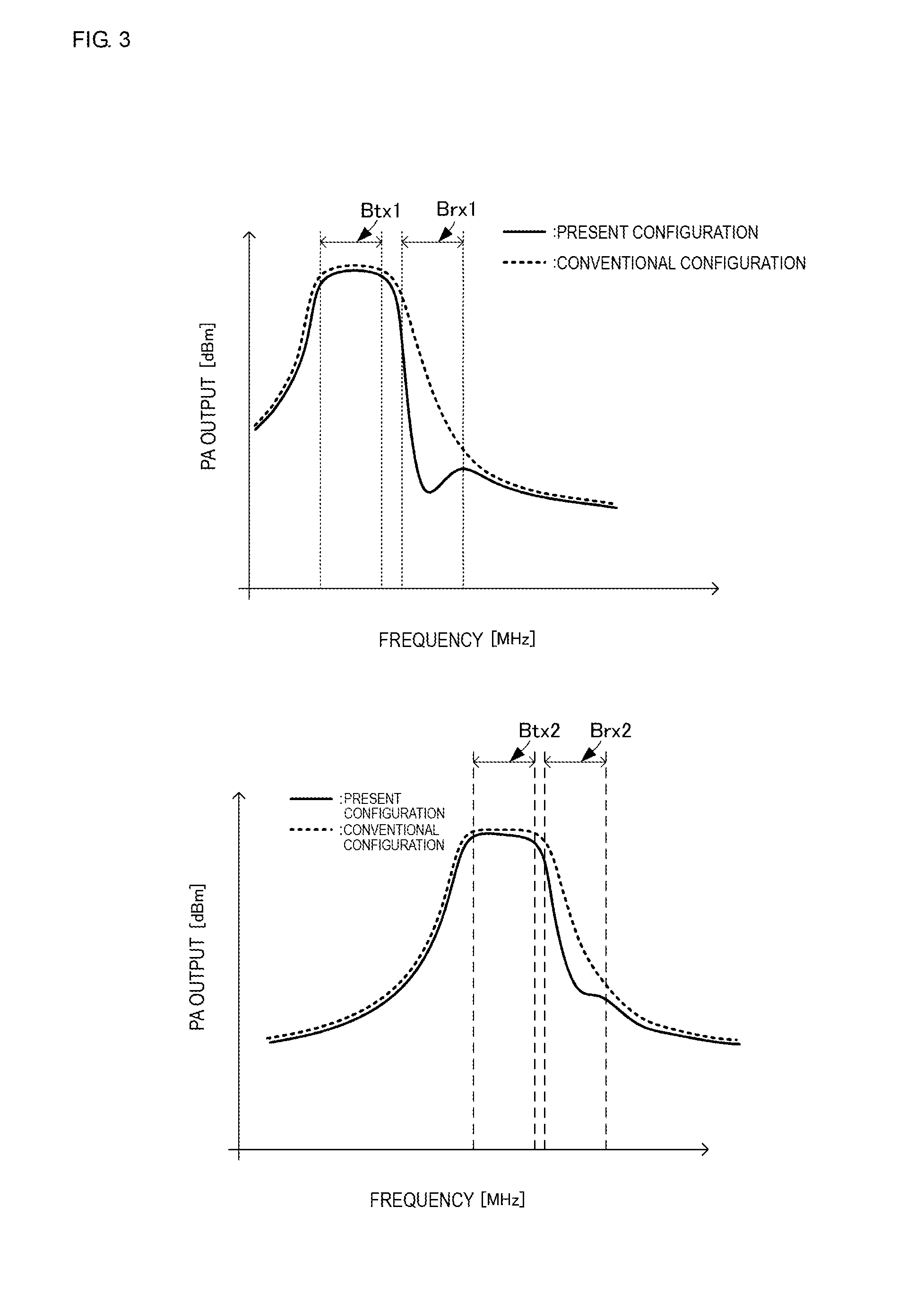
[0046]The high frequency power amplifier 10 having this configuration operates as described below. FIG. 3 is graphs showing the output characteristics of the high frequency power amplifier according to the present disclosure. In FIG. 3, horizontal axes represent a frequency, and vertical axes represent an output level. In FIG. 3, solid lines represent the case of the configuration of the present disclosure, and dotted lines represent the case of a conventional configuration.

[0047](Transmission and Reception Using First Communication Band)

[0048]The transmission circuit 51 generates the first transmission signal, and outputs the first transmission signal to the high frequency power amplifier 10. The first high frequency amplifier 11 amplifies the first transmission signal and outputs the amplified first transmission signal. Since the first high frequency amplifier 11 is a wide band high frequency amplifier corresponding to at least two or more communication bands, the first high frequ...

fourth embodiment

[0081]Next, a high frequency front-end circuit and a radio communication device according to the present disclosure will be described with reference to the drawings.

[0082]The branching filter 30 is used in each of the above embodiments. However, in this embodiment, a transmission antenna and a reception antenna are individually used without necessarily using the branching filter 30. FIG. 7 is a circuit block diagram of the radio communication device according to the fourth embodiment of the present disclosure.

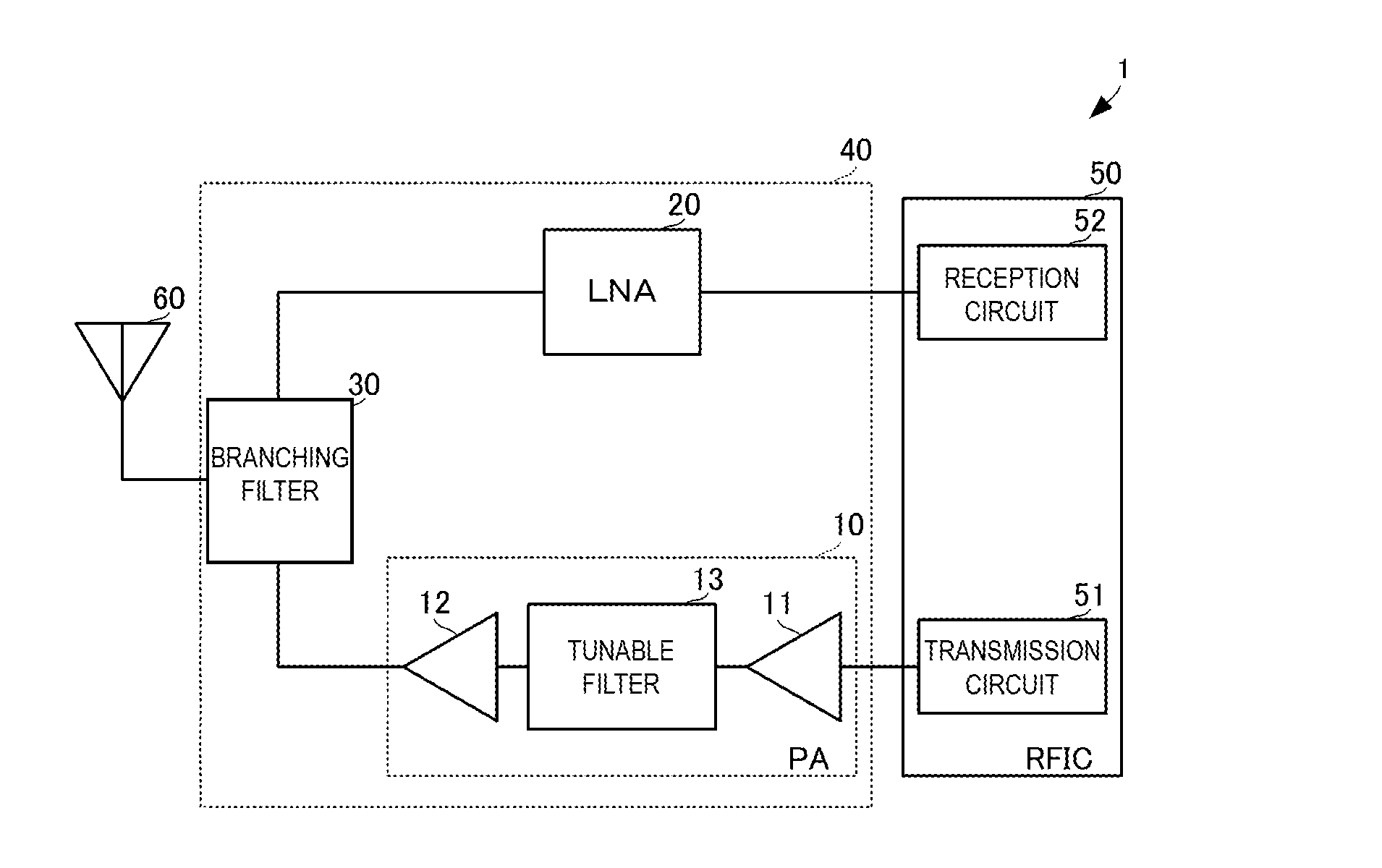
[0083]As shown in FIG. 7, a radio communication device 1C includes a high frequency front-end circuit 40C, the RFIC 50, a transmission antenna 61, and a reception antenna 62.

[0084]The high frequency front-end circuit 40C includes the high frequency power amplifier 10 and the LNA 20. The input terminal of the high frequency power amplifier 10 is connected to the transmission circuit 51 of the RFIC 50, and the output terminal of the high frequency power amplifier 10 is connected ...


PUM


Abstract

A high frequency power amplifier includes a first high frequency amplifier, a final high frequency amplifier, and a tunable filter. The tunable filter is connected between the first high frequency amplifier and the final high frequency amplifier. The first high frequency amplifier and the final high frequency amplifier are each a multimode / multiband power amplifier. The tunable filter is regulated such that its pass band includes the frequency band of a transmission signal and its attenuation band includes the frequency band of a reception signal in a communication band used in transmission and reception. The pass band and the attenuation band are switched by the tunable filter in accordance with the communication band used in transmission and reception.

Description

BACKGROUND[0001]Technical Field[0002]The present disclosure relates to a high frequency power amplifier for amplifying a high frequency signal, a high frequency front-end circuit including the high frequency power amplifier, and a radio communication device using the amplified high frequency signal as a transmission signal.[0003]In accordance with diversification of communication bands, various types of high frequency front-end circuits and radio communication devices using a multimode / multiband power amplifier for amplifying transmission signals of a plurality of bands have been proposed as described in, for example, Patent Document 1. The multimode / multiband power amplifier is designed such that a desired gain is obtained in each of the plurality of frequency bands, and the desired gains are thereby obtained in a wide band (wide frequency band).[0004]The high frequency front-end circuits and the radio communication devices each include a receiver side circuit that includes a low n...

Claims


Application Information

Patent Timeline
IPC IPC(8): H04B1/04H03F3/24H03F3/21H03F3/195
CPCH04B1/0475H03F3/195H03F3/245H03F3/211H03F2200/111H03F2200/294H03F2200/168H03F2203/21157H03F2200/451H03F2200/408H03F2200/165H03F2200/171H03F2200/411H04B1/525
Inventor OBIYA, HIDENORIHAYAFUJI, HISAOWADA, TAKAYAHITOMI, SHINYA
Owner MURATA MFG CO LTD
Why Eureka
Try Eureka