
Night vision system and method

a technology of night vision and system, applied in the field of extended thermal imaging, can solve the problems of increasing the system size, weight, cost and power consumption of the system, and the inability to cool the detector,

Active Publication Date: 2014-02-13
ELTA SYST LTD
View PDF4 Cites 3 Cited by
  • Summary
  • Abstract
  • Description
  • Claims
  • Application Information

AI Technical Summary

Benefits of technology

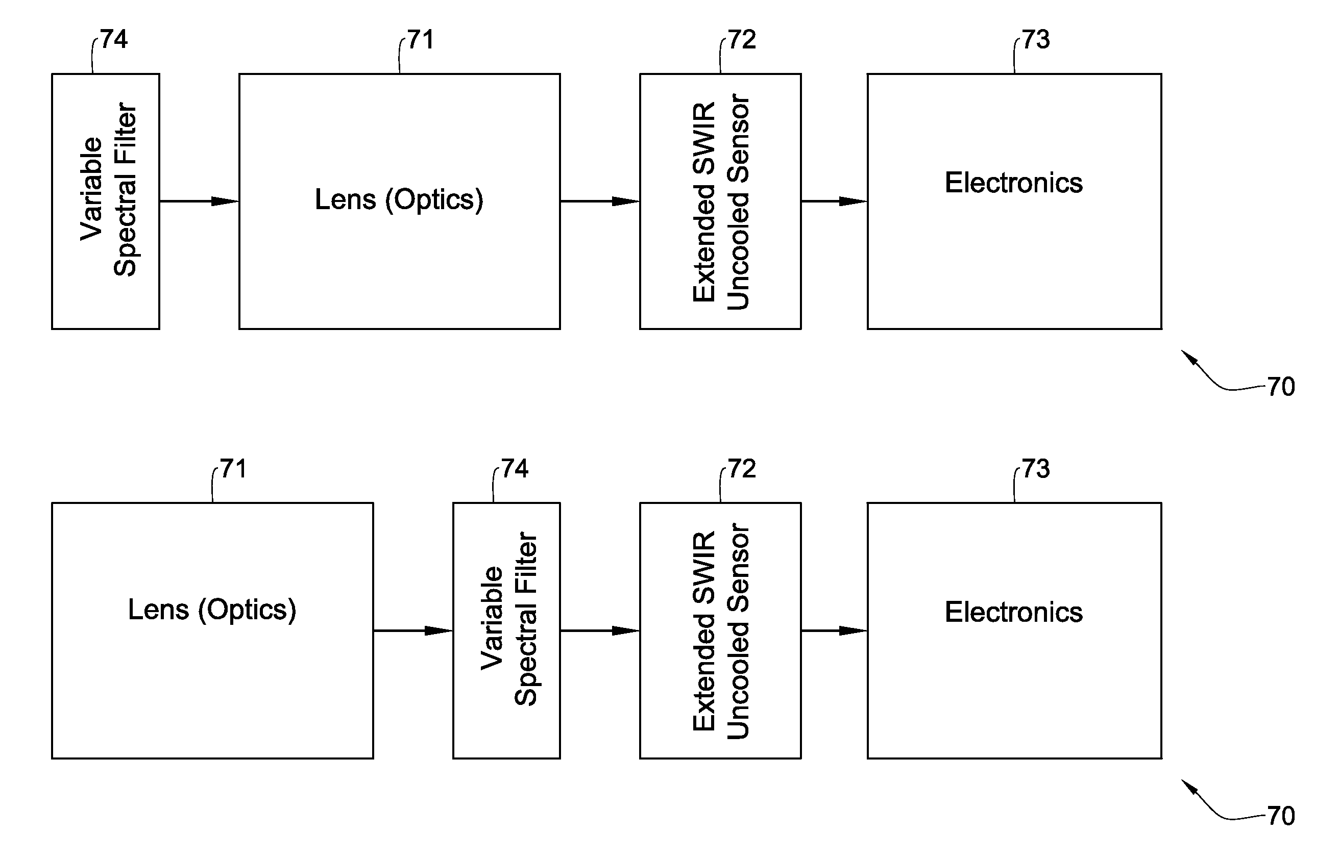
The present invention provides a new night vision system that can operate at or near room temperature and in the wavelength region up to 2.5 microns. The system uses an optical system to collect and focus light onto a photodetector. A spectral filter is used to separate reflective and thermal information, allowing for different modes of operation depending on the user's needs. The system can detect both reflected and emitted light from the object being imaged, providing a more accurate and reliable image. The invention also includes a method for shifting between reflection and thermal modes to improve imaging performance.

Problems solved by technology

Infrared detectors are widely used for collecting image information under conditions which do not allow regular optical observation, such as at night or through clouds, haze or dust.
As known in the art, cooling the detector increases the system size, weight, cost and power consumption of the system.
Therefore, cooled detectors are not a viable solution when these resources are limited.
On the other hand, conventional un-cooled detectors have insufficient sensitivity and dark / background current, which are insufficient for night vision in the 1-2.5 μm spectral range.
These types of imaging techniques have several disadvantages, such that neither one of them is considered superior in all respects and all scenarios.

Method used


Image

  • Night vision system and method
  • Night vision system and method
  • Night vision system and method

Examples


Embodiment Construction

[0040]In the following detailed description, numerous specific details are set forth in order to provide a thorough understanding of the invention. However, it will be understood by those skilled in the art that the present invention may be practiced without these specific details. In other instances, well-known methods, procedures, and components have not been described in detail so as not to obscure the present invention.

[0041]In the drawings and descriptions set forth, identical reference numerals indicate those components that are common to different embodiments or configurations.

[0042]As used herein, the phrase “for example,”“such as”, “for instance” and variants thereof describe non-limiting embodiments of the presently disclosed subject matter. Reference in the specification to “one case”, “some cases”, “other cases” or variants thereof means that a particular feature, structure or characteristic described in connection with the embodiment(s) is included in at least one embod...


PUM

PropertyMeasurementUnit
wavelengthaaaaaaaaaa
cut-off wavelengthaaaaaaaaaa
wavelengthsaaaaaaaaaa

Abstract

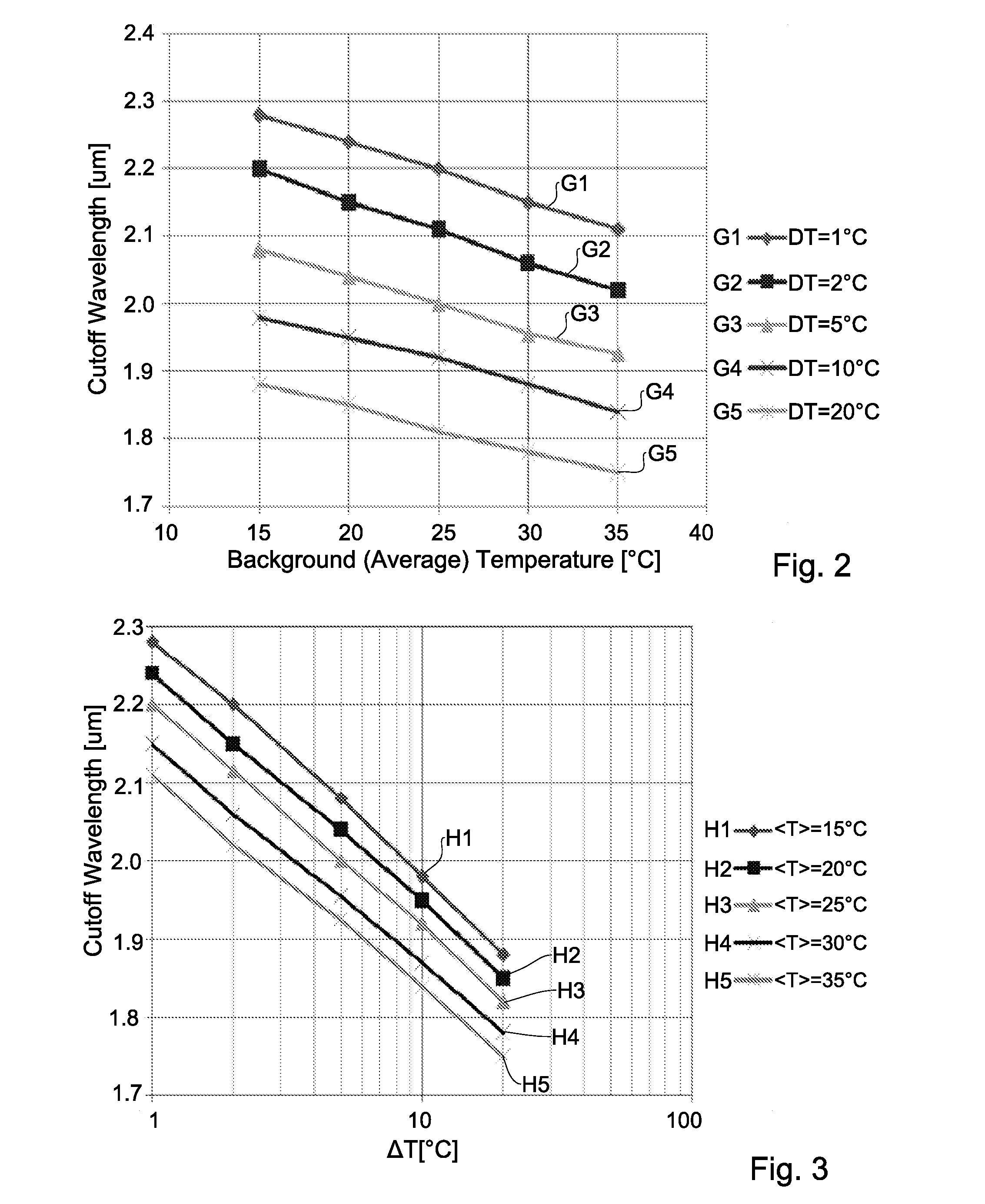
A night vision system and method for imaging an object at or near room temperature and in the wavelength region up to 2.5 microns is described. The includes a photodetector having a cut-off wavelength of 2.5 microns under the room temperature, an optical system configured for collecting light and focusing the collected light onto the photodetector, and a spectral filter located in an optical path of light propagating toward the photodetector. The spectral filter is configured and operable to selectively filter out light of wavelength shorter than a predetermined value, thereby gradually shifting operation of the night vision system from mostly reflection mode to a combined reflection and thermal mode, to allow the night vision system to detect light reflected from and emitted by the object being imaged.

Description

FIELD OF THE INVENTION[0001]This invention relates to systems and methods for extended thermal imaging, and more particularly to systems and methods for short wave Infrared (SWIR) imaging.BACKGROUND OF THE INVENTION[0002]Infrared detectors are widely used for collecting image information under conditions which do not allow regular optical observation, such as at night or through clouds, haze or dust. For example night vision detectors allow car drivers to watch beyond the reach of the car headlamps illumination field, for search and rescue operations and other applications.[0003]Traditionally the infrared band is divided to Near IR (NIR) between 0.75 μm and 1.1 μm, Short Wavelength IR-1 (SWIR-1) optical band about 1.1 μm-1.7 μm, and Short Wavelength IR-2 (SWIR-2) optical band about 1.7 μm-2.5 μm, Mid Wave IR (MWIR) between 3 μm and 5 μm and Long wave IR (LWIR) between 8 μm and 14 μm.[0004]SWIR detectors are used for various civilian and military applications including night vision, ...

Claims


Application Information

Patent Timeline
Patent Type & Authority Applications(United States)
IPC IPC(8): H04N5/33
CPCH04N5/33H01L27/1465H01L27/14652H04N23/23H04N23/11
Inventor TIDHAR, GIL
Owner ELTA SYST LTD
Learn More