Device for, and method of, blocking emboli in vessels such as blood arteries

a technology of emboli and vessels, applied in the field of devices and methods for blocking emboli in vessels such as blood arteries, can solve the problems of emboli trace release damage, trapped emboli to escape from the filter, and limited attempts to treat lesions in the carotid arteries, so as to prevent the backflow of trapped emboli into the vessel and the risk of losing any trapped emboli is small

Inactive Publication Date: 2011-04-05
ABBOTT CARDIOVASCULAR
View PDF773 Cites 11 Cited by
  • Summary
  • Abstract
  • Description
  • Claims
  • Application Information

AI Technical Summary

Benefits of technology

[0008]A directional member, attached to the filtering member, has a length extending at least to the vessel wall. This directional member can be made from a pliable and elongatable material with properties of blocking fluid and emboli passage. The directional member is disposed to direct the fluid and any emboli in the fluid into the filtering member. The filtering and directional members generally are disposed at an acute angle relative to the shaft. The directional member is designed to create a deep pocket which is used to trap the emboli while allowing the fluid to pass there through to downstream vessels. In one particular embodiment, the directional member has a conical shape which acts much like a parachute when deployed in the fluid flow. The directional member opens up when subjected to the fluid flow and remains in a fully deployed position to partially occlude the vessel, due to fluid build proximal to the directional member. The filtering member located within the deep pocket formed by the directional member provides the filtering media for trapping the emboli. In this fashion, the directional member is designed to channel all fluid and emboli into the deep pocket to allow the filtering member to perform the necessary filtration. The design of the deep pocket helps to retain the emboli deep within the filtering device, sufficiently past the inlet opening of the directional member. As a result, there is a less possibility that trapped emboli will “backflow” into the artery as the filtering portion of the device is being collapsed and removed from the patient's vasculature.
[0010]In one aspect of the invention, the catheter portion of the filtering device includes an outer sheath or sleeve which extends co-axially over the filtering portion of the device. The filtering portion can be deployed from the confides of the sheath by simply moving the inner shaft of the catheter portion in an outward direction from the sheath, or by retracting the sheath, or a combination of both. Once the inlet opening of the directional member is deployed in the fluid flow, it will expand outwardly (like a deployed parachute) within the vessel. Restraining wires, attached to the directional member near its inlet opening extend along the catheter portion to a location outside the patient. When the device is to be collapsed and removed from the patient, the physician simply retracts these wires to collapse the directional member and draw at least a portion of the directional member (including the inlet opening) back into the lumen of the outer sheath. This helps prevent backflow of trapped emboli into the vessel. Any trapped emboli which is capable of backflowing from the filtering portion will now be trapped within the inner lumen of the sheath and will not be discharged into the vessel. Thereafter, the entire device can be removed from the patient with little risk of losing any trapped emboli.

Problems solved by technology

In the process of expanding such blood vessels at the positions of the lesions, emboli may become detached from the lesions and enter the bloodstream and subsequently migrate through the patient's vasculature to cut off or reduce the amount of oxygenated blood being supplied to sensitive organs such as the brain, which may induce trauma.
Unfortunately, it is possible for some of the trapped emboli to escape from the filter during the time that the filter is being collapsed and / or removed from the blood vessel.
When an interventional procedure is being performed in a carotid artery, even a trace release of emboli can be damaging.
For these reasons, attempts to treat lesions in the carotid arteries have been somewhat limited due to the danger presented if all of the embolic debris is not collected during the procedure.

Method used


Image

  • Device for, and method of, blocking emboli in vessels such as blood arteries
  • Device for, and method of, blocking emboli in vessels such as blood arteries
  • Device for, and method of, blocking emboli in vessels such as blood arteries

Examples


Embodiment Construction

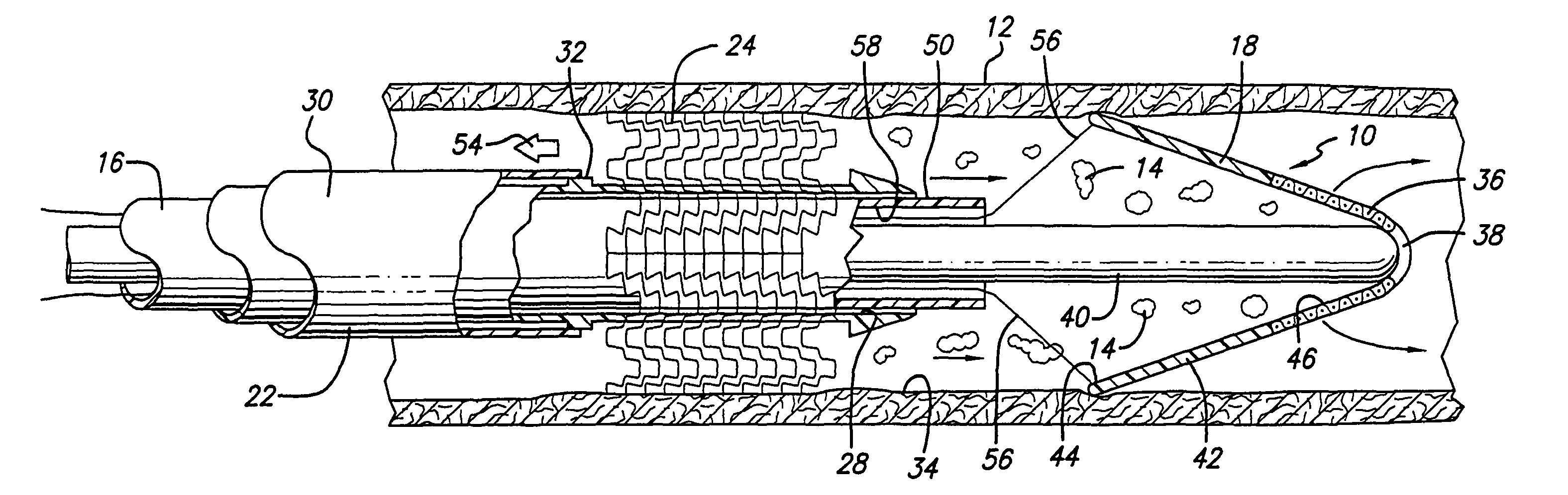
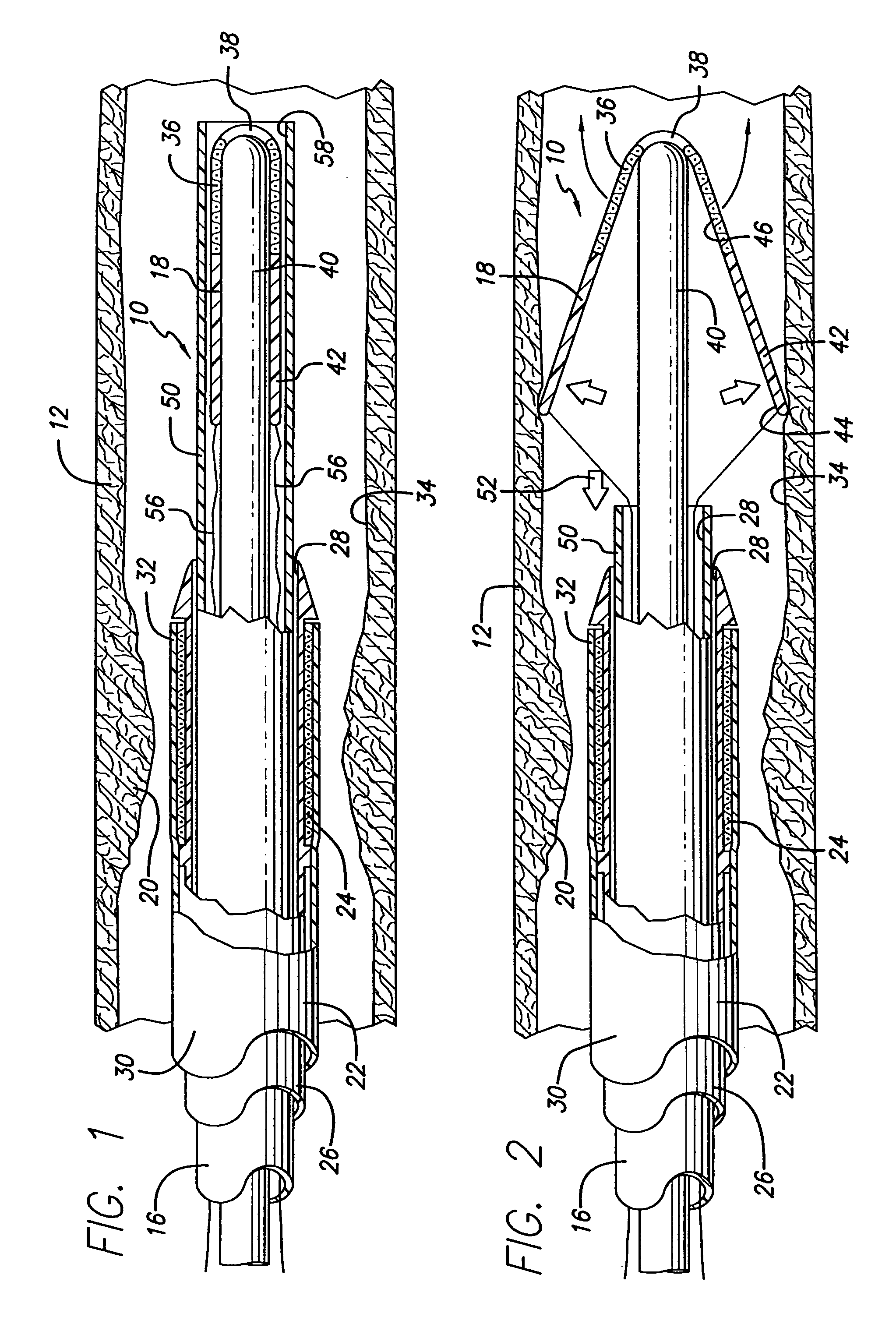
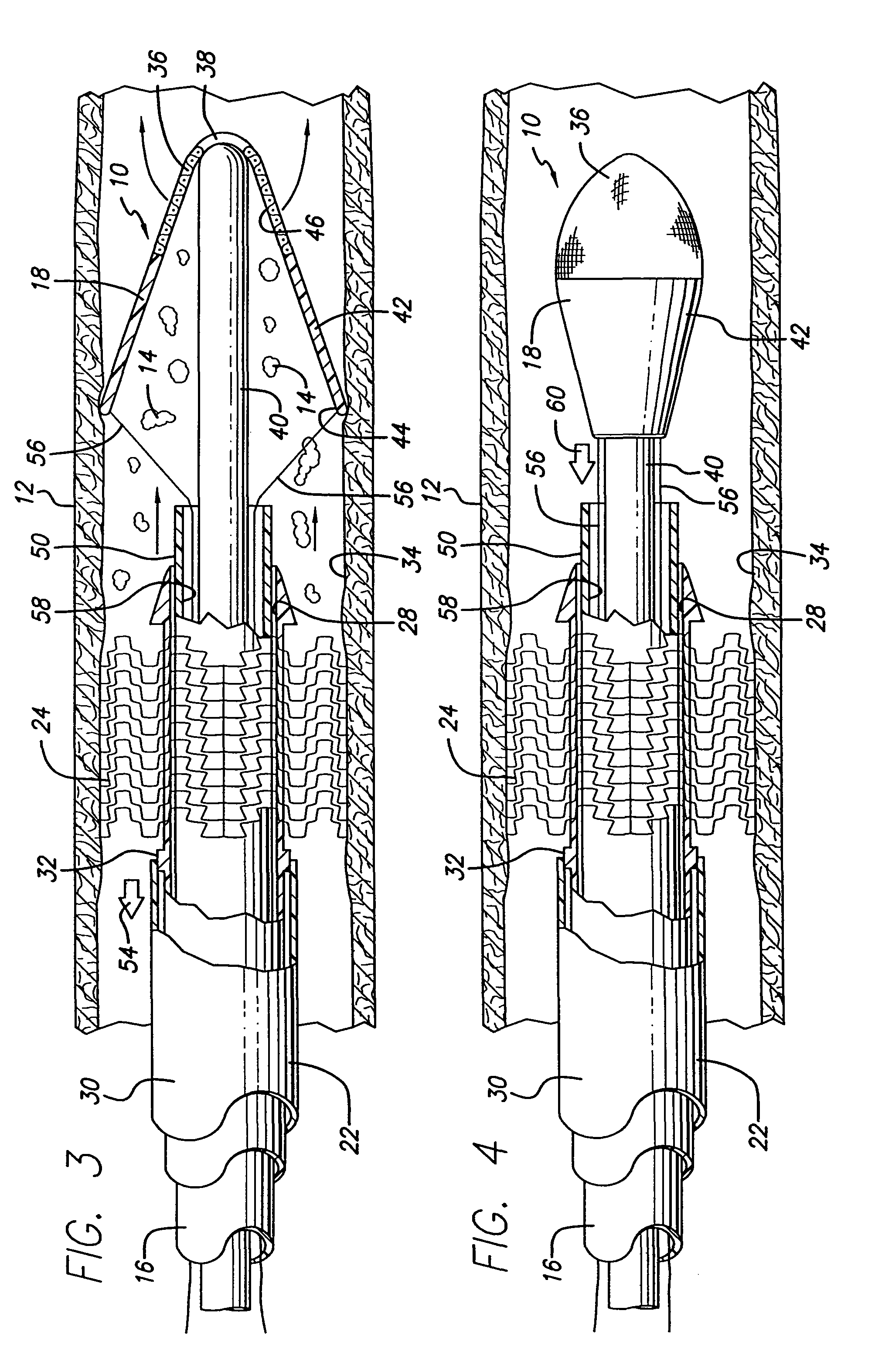
[0017]A first preferred embodiment of a filtering device made in accordance with the present invention, generally indicated at 10, is shown in FIGS. 1-5 of the drawings. The filtering device 10 is adapted to be disposed in a blood vessel 12 to pass the blood in the vessel and block the passage of emboli 14 (FIG. 3) in the blood. The filtering device 10 includes a catheter portion 16 which is designed to deploy a filtering portion 18 in the vessel 12 to trap and remove emboli 14 from the vessel. The emboli 14 are produced when the vessel 12 is treated at the position of a lesion 20 during an intervention procedure such as, a balloon angioplasty procedure, a stenting procedure, an atherectomy procedure and the like. The present invention is designed to collect and remove such embolic debris from the artery to prevent the blockage of the smaller vessels downstream from the area of treatment. The system 10 is especially adapted to prevent blockage of small blood vessels leading to the b...


PUM


Abstract

A filtering device has a directional member and filtering member disposable in a vessel (e.g. blood artery) at a position past a lesion in the direction of fluid flow. The filtering member is made from a resilient material having properties of passing the fluid while blocking the passage of emboli in the fluid. This material may be selected from a group consisting of blood filter material and a braided / woven biocompatible material with the properties specified above. The inner end of the filtering member is attached to a shaft which provides for the disposition of the members in the vessel at the position past the lesion and the withdrawal of the members from the vessel. The directional member has a length extending at least to the vessel wall. The directional member is made from a pliable and elongatable material with properties of blocking fluid and emboli passage. The directional member is deployable within the vessel by the fluid flow in the vessel and directs the fluid in the vessel and any emboli in the fluid into the filtering member. The filtering and directional members are disposed at an acute angle relative to the shaft to create a trapping pocket. Restraining wires attached to the directional member are used to collapse the directional member and draw at least a part of the directional member into an outer sheath to prevent emboli from backflowing into the vessel.

Description

CROSS-REFERENCE TO RELATED APPLICATIONS[0001]This application is a continuation of U.S. Ser. No. 09 / 476,689, filed Dec. 30, 1999. The contents of which are hereby incorporated by reference.BACKGROUND OF THE INVENTION[0002]This invention relates to a device for, and methods of, preventing emboli from a lesion in a vessel from passing through the vessel. The device and method of the present invention are especially adapted to be used in preventing emboli in blood from passing through a vessel such as an artery.[0003]In recent years, numerous procedures have been adapted for expanding blood vessels (e.g. arteries), at the positions of lesions in the blood vessels, so that blood can flow through the blood vessels without obstruction from the lesions. In the process of expanding such blood vessels at the positions of the lesions, emboli may become detached from the lesions and enter the bloodstream and subsequently migrate through the patient's vasculature to cut off or reduce the amount...

Claims


Application Information

Patent Timeline
Patent Type & Authority Patents(United States)
IPC IPC(8): A61M29/00
CPCA61F2/013A61F2/966A61F2/95A61F2/958A61F2230/008A61F2002/018A61F2230/0006A61F2230/0067
Inventor STALKER, KENT C. B.
Owner ABBOTT CARDIOVASCULAR
Why Eureka
Try Eureka