System stability and performance improvement with anode heat exchanger plumbing and re-circulation rate

a heat exchanger and anode technology, applied in the field of fuel cell systems, can solve the problems of reducing the overall efficiency of the fuel cell, water accumulation within the fuel cell, and reducing the electricity produced by the fuel cell, so as to reduce the formation of water droplets, increase stack stability, and reduce the amount of liquid water droplets

Inactive Publication Date: 2011-04-05
GM GLOBAL TECH OPERATIONS LLC
View PDF3 Cites 2 Cited by
  • Summary
  • Abstract
  • Description
  • Claims
  • Application Information

AI Technical Summary

Benefits of technology

[0010]In accordance with the teachings of the present invention, a fuel cell system is disclosed that increases stack stability by reducing the amount of liquid water droplets at the anode input of a fuel cell stack in the system. Re-circulated anode exhaust gas from the fuel cell stack and fresh hydrogen gas are sent to an anode heat exchanger so that both the fresh hydrogen gas and the re-circulated anode exhaust gas are heated to reduce the formation of water droplets in the anode input gas. Further, a portion of the heated cooling fluid directly from the fuel cell stack is sent to the anode heat exchanger to heat the fresh hydrogen gas and the re-circulation hydrogen before the cooling fluid is sent to an isolation heat exchanger to have its temperature reduced.

Problems solved by technology

At low power demands, typically below 0.2 A / cm2, the water may accumulate within the flow channels because the flow rate of the reactant gas is too low to force the water out of the channels.
Those areas of the membrane that do not receive reactant gas as a result of the channel being blocked will not generate electricity, thus resulting in a non-homogenous current distribution and reducing the overall efficiency of the fuel cell.
As more and more flow channels are blocked by water, the electricity produced by the fuel cell decreases, where a cell voltage potential less than 200 mV is considered a cell failure.
The liquid water droplets then enter the anode reactant gas flow channels possibly causing cell stability problems as discussed above.

Method used


Image

  • System stability and performance improvement with anode heat exchanger plumbing and re-circulation rate
  • System stability and performance improvement with anode heat exchanger plumbing and re-circulation rate
  • System stability and performance improvement with anode heat exchanger plumbing and re-circulation rate

Examples


Embodiment Construction

[0014]The following discussion of the embodiments of the invention directed to a fuel cell system that uses heated cooling fluid to heat the anode input gas is merely exemplary in nature, and is in no way intended to limit the invention or its applications or uses.

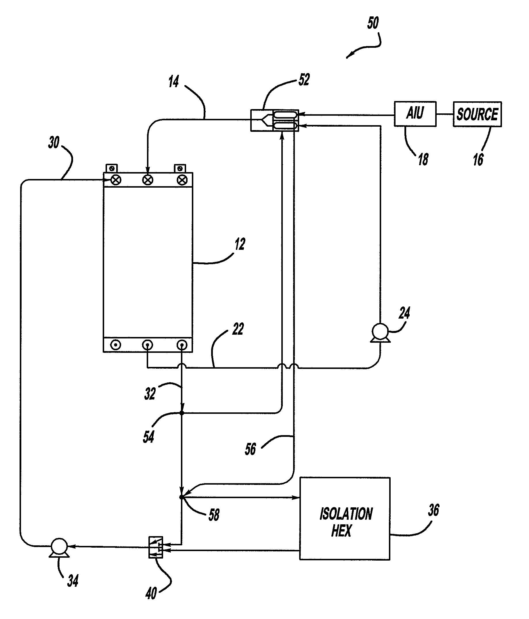
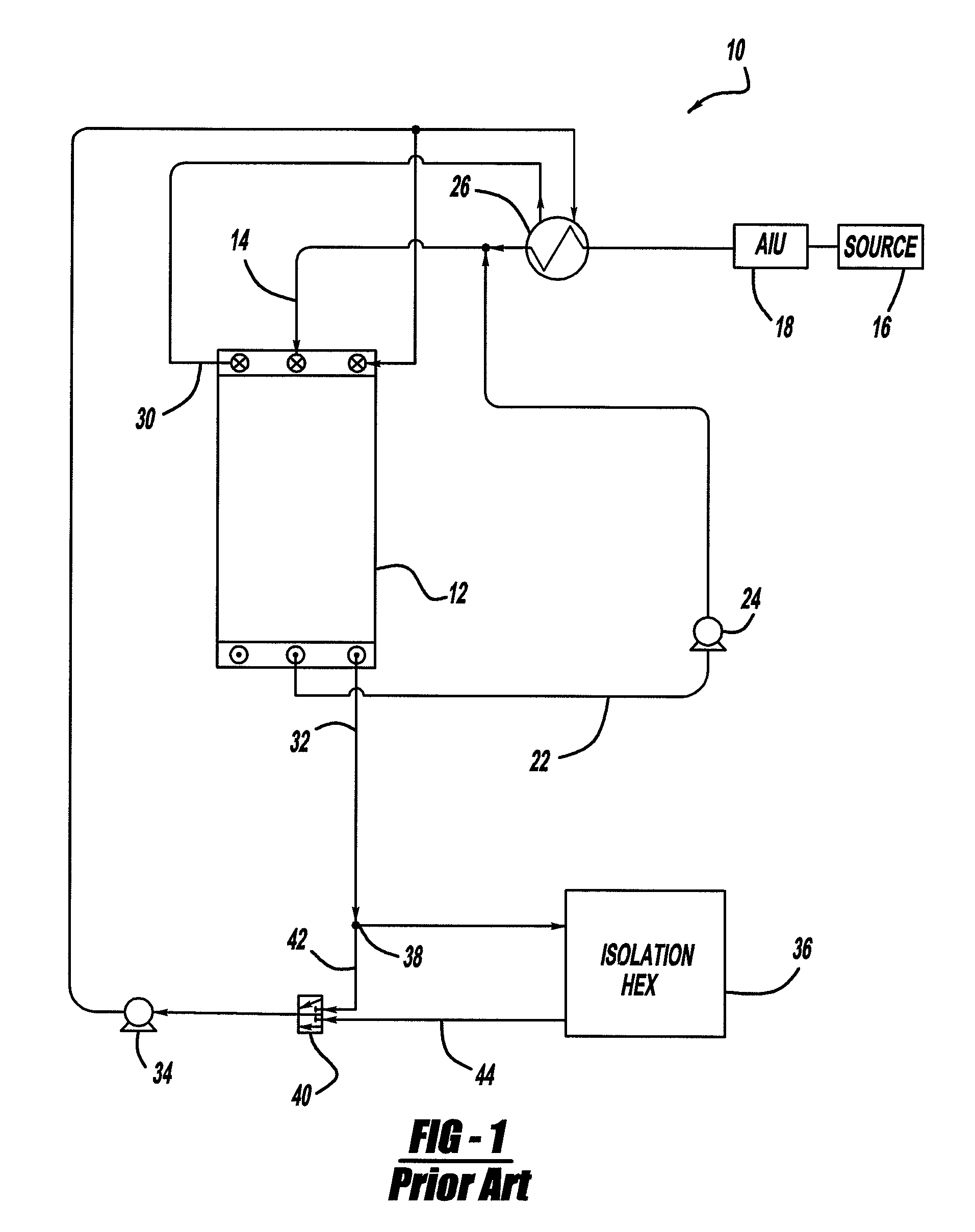
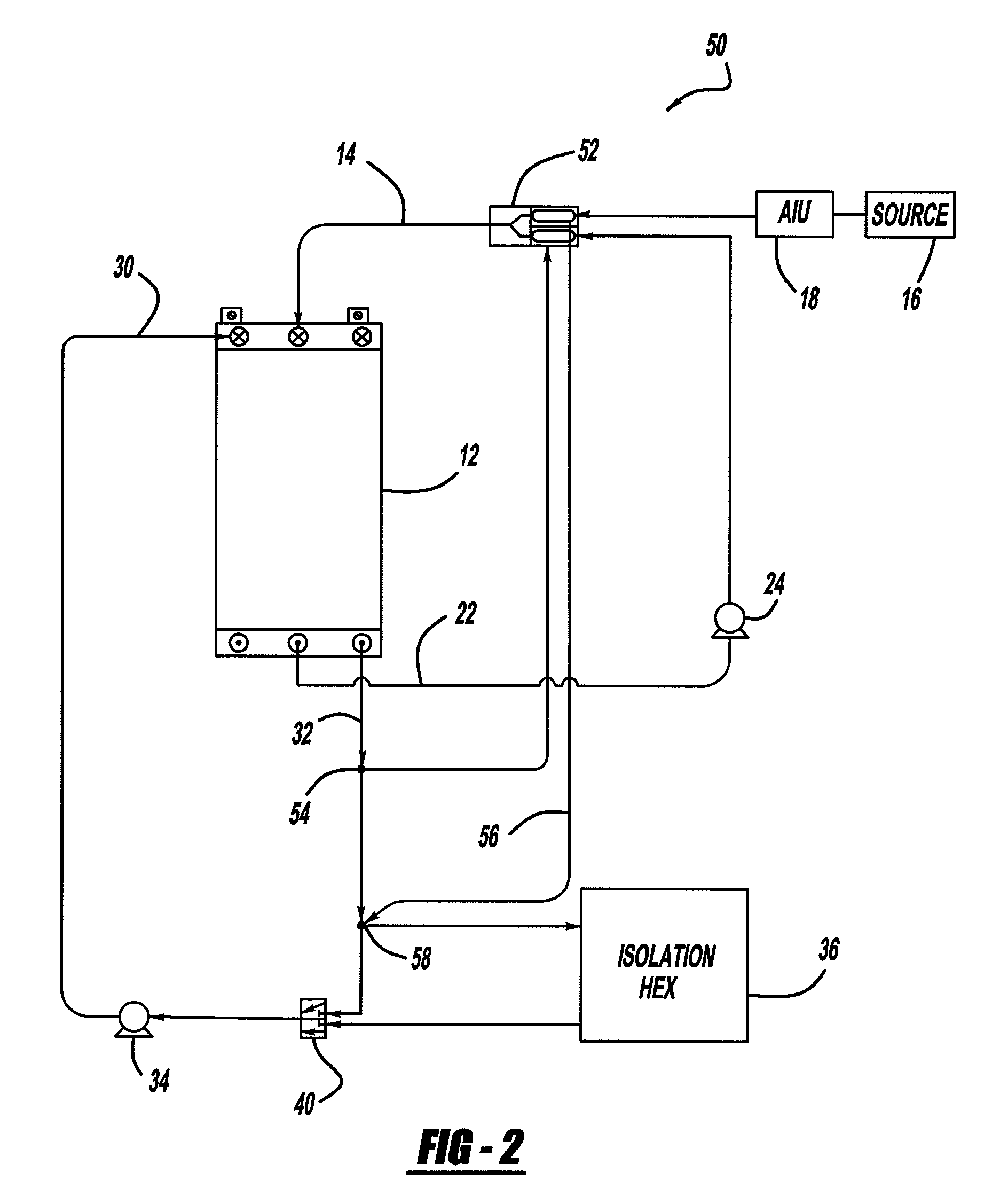
[0015]FIG. 1 is a schematic diagram of a known fuel cell system 10 of the type discussed above. The cathode side of the system 10 is not shown for clarity purposes. The fuel cell system 10 includes a fuel cell stack 12 that receives a hydrogen reactant gas flow on line 14 from a hydrogen source 16, such as a compressed gas tank. The hydrogen gas from the source 16 is sent to an anode inlet unit (AIU) 18 that injects the hydrogen gas into the fuel cell stack 12 at the desired flow rate and pressure. In this design, anode exhaust gas is output from the stack 12 on line 22 and is re-circulated back to the input line 14 by a pump 24 to reclaim the un-reacted hydrogen. The anode exhaust gas from the fuel cell stack 12 is heated...


PUM

PropertyMeasurementUnit
temperatureaaaaaaaaaa
cell voltage potentialaaaaaaaaaa
stabilityaaaaaaaaaa

Abstract

A fuel cell system that increases stack stability by reducing the amount of liquid water droplets at the anode input of a fuel cell stack in the system. Re-circulated anode exhaust gas from the fuel cell stack and fresh hydrogen gas are sent to an anode heat exchanger so that both the fresh hydrogen gas and the re-circulated anode exhaust gas are heated to reduce the formation of water droplets in the anode input gas. Further, a portion of the heated cooling fluid directly from the fuel cell stack is sent to the heat exchanger to heat the fresh hydrogen gas and the re-circulation hydrogen before the cooling fluid is sent to an isolation heat exchanger to have its temperature reduced.

Description

BACKGROUND OF THE INVENTION[0001]1. Field of the Invention[0002]This invention relates generally to a fuel cell system that heats an anode re-circulation gas for preventing water droplets from forming to improve system stability and, more particularly, to a fuel cell system that uses a heated cooling fluid directly from the stack to heat an anode re-circulation gas for preventing water droplets from forming to improve system stability.[0003]2. Discussion of the Related Art[0004]Hydrogen is a very attractive fuel because it is clean and can be used to efficiently produce electricity in a fuel cell. A hydrogen fuel cell is an electro-chemical device that includes an anode and a cathode with an electrolyte therebetween. The anode receives hydrogen gas and the cathode receives oxygen or air. The hydrogen gas is dissociated in the anode to generate free protons and electrons. The protons pass through the electrolyte to the cathode. The protons react with the oxygen and the electrons in t...

Claims


Application Information

Patent Timeline
Patent Type & Authority Patents(United States)
IPC IPC(8): H01M8/00
CPCH01M8/04014H01M8/04029H01M8/04119H01M8/04097Y02E60/50
Inventor MACHUCA, JOE C.ALP, ABDULLAH B.
Owner GM GLOBAL TECH OPERATIONS LLC
Why Eureka
Try Eureka