Synchronized vibration device for haptic feedback
a technology of haptic feedback and vibration device, which is applied in the direction of motor/generator/converter stopper, dynamo-electric converter control, dynamo-electric gear control, etc., can solve the problem of not being able to modify the magnitude of vibration for a given vibration frequency, cannot be operated in time, and the force sensation is limited
- Summary
- Abstract
- Description
- Claims
- Application Information
AI Technical Summary
Problems solved by technology
Method used
Image
Examples
embodiment 600
[0221]An embodiment 600 of the present invention with a haptic interface application is shown in FIG. 37. In this embodiment a systems controller 602 provides force commands to a haptic interface 604 which generates forces which result in force sensations to user 606. The systems controller 602 may be microprocessor, a central processing unit, an ASIC, a DSP, a game controller, an analog controller, or other type of controller or any combination thereof. The user 606 can input commands to the haptic interface 604 that are transmitted as user commands back to the system controller 602. The user commands can be input through pressing buttons, moving joysticks, squeezing the haptic interface at various level forces, moving the haptic interface, applying force and torque onto the haptic interface and through other means.
[0222]In the embodiment shown in FIG. 37, there is preferably a graphical display 608 which receives an image command from the system controller 602 and displays a visua...
embodiment 620
[0224]Another embodiment 620 having a haptic interface application is shown in FIG. 38. This embodiment is similar to the one of FIG. 37, and includes a systems controller 622, which provides force commands to a haptic interface 624 that generates forces which result in force sensations being received by user 626. A graphical display 628 is also provided for receiving image commands from the system controller 622 and for displaying a visual image to the user 626.
[0225]In the embodiment of FIG. 38, the haptic interface 624 desirably includes a vibration device 630 having vibration actuators (not shown), a vibration controller 632, driver circuits 634 which drive the vibration device actuators, and an input device 636, which can detect user input and which can include buttons, joysticks, and pressure sensors. The components of the haptic interface 624 may be of any of the configurations described herein. In this embodiment the graphical display 628 preferably presents a two dimensiona...
embodiment 710
[0257]To further simplify the vibration controller circuitry and lower cost, the amplitude of the vibration signal can be modulated with a PWM signal, where the duty cycle of the signal is proportional to the amplitude of vibration. An embodiment 710 with such a digital vibration controller 712 for one actuator 716 is shown in FIG. 41. In this embodiment, the output of the digital vibration controller 712 includes an amplitude signal in PWM form and a direction signal, for instance in the form of a logic bit, both of which preferably are sent to a driver circuit 714. The driver circuit 714, in turn, sends electrical power to the actuator 716.
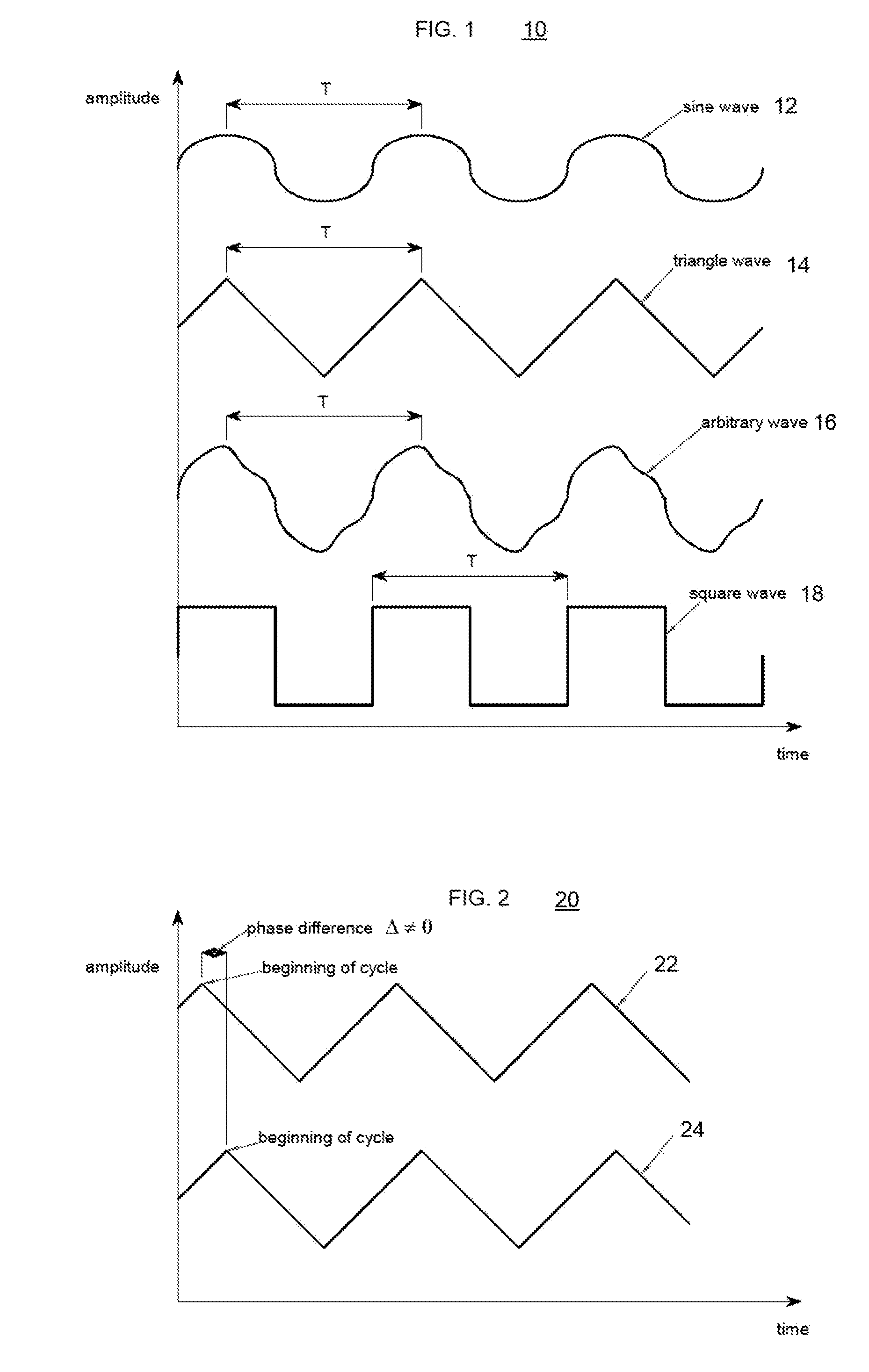
[0258]Digital control circuitry can be used to control a complete vibration device in synchronized vibration. In synchronized vibration the frequency and phase of two or more actuators are the same. Accordingly, a single square wave can be used to control the direction of the vibration actuators that are in synchronized vibration. The amplitude ...
PUM
 Abstract
Description
Claims
Application Information
 - R&D
- Intellectual Property
- Life Sciences
- Materials
- Tech Scout
- Unparalleled Data Quality
- Higher Quality Content
- 60% Fewer Hallucinations
Browse by: Latest US Patents, China's latest patents, Technical Efficacy Thesaurus, Application Domain, Technology Topic, Popular Technical Reports.
© 2025 PatSnap. All rights reserved.Legal|Privacy policy|Modern Slavery Act Transparency Statement|Sitemap|About US| Contact US: help@patsnap.com


