Method and apparatus for estimating the velocity vector of multiple vehicles on non-level and curved roads using a single camera

a technology of velocity vector and camera, applied in the field of measuring the position, velocity vector, speed and direction of moving vehicles, can solve the problems of millions of americans being injured each year and millions of americans dying

Active Publication Date: 2011-04-05
WILLIAMS CHRISTOPHER REED
View PDF54 Cites 50 Cited by
  • Summary
  • Abstract
  • Description
  • Claims
  • Application Information

AI Technical Summary

Benefits of technology

[0010]Additionally, the present invention estimates the vehicle velocity vector, which is composed of the vehicle speed and vehicle direction, in the three-dimensional real world. Estimating the vehicle velocity vector enables the vehicle speed to be estimated over non-straight roads. Thus, contrary to the Prior Art, the present invention estimates the vehicle speed of vehicles traveling on curved roads.
[0011]Furthermore, estimating the vehicle velocity vector enables the vehicle speed to be estimated as the vehicle travels on a road that changes elevation. Thus, contrary to the Prior Art, the present invention estimates the vehicle speed of vehicles traveling on roads that change elevation.
[0012]Further advantages of the present invention will become apparent from a consideration of the drawings and the ensuing description.
[0013]The present invention uses passive remote sensing technology and image processing techniques to identify and quantify the three-dimensional movement of multiple moving vehicles observed by a two-dimensional optical observing system. The present invention uses one camera mounted above a roadway system to observe vehicles traveling on different roads. Using the camera tilt angle, the camera pan angle, and the camera lens zoom characteristics, each pixel in the two-dimensional optical image is assigned a unique pixel tilt angle and pixel pan angle. A survey of the roadway system provides the elevation of the individual roads re

Problems solved by technology

Thousands of Americans die and millions of Americans are injured each year in auto

Method used


Image

  • Method and apparatus for estimating the velocity vector of multiple vehicles on non-level and curved roads using a single camera
  • Method and apparatus for estimating the velocity vector of multiple vehicles on non-level and curved roads using a single camera
  • Method and apparatus for estimating the velocity vector of multiple vehicles on non-level and curved roads using a single camera

Examples


Embodiment Construction

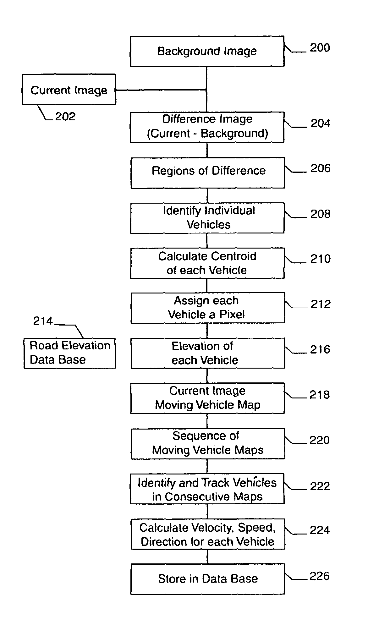
[0028]The preferred embodiment of the present invention will be explained with reference to FIGS. 1 to 10. Identical parts are denoted by the same reference numerals throughout the views.

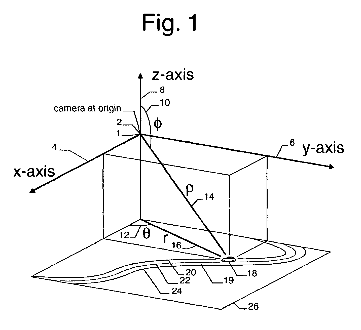
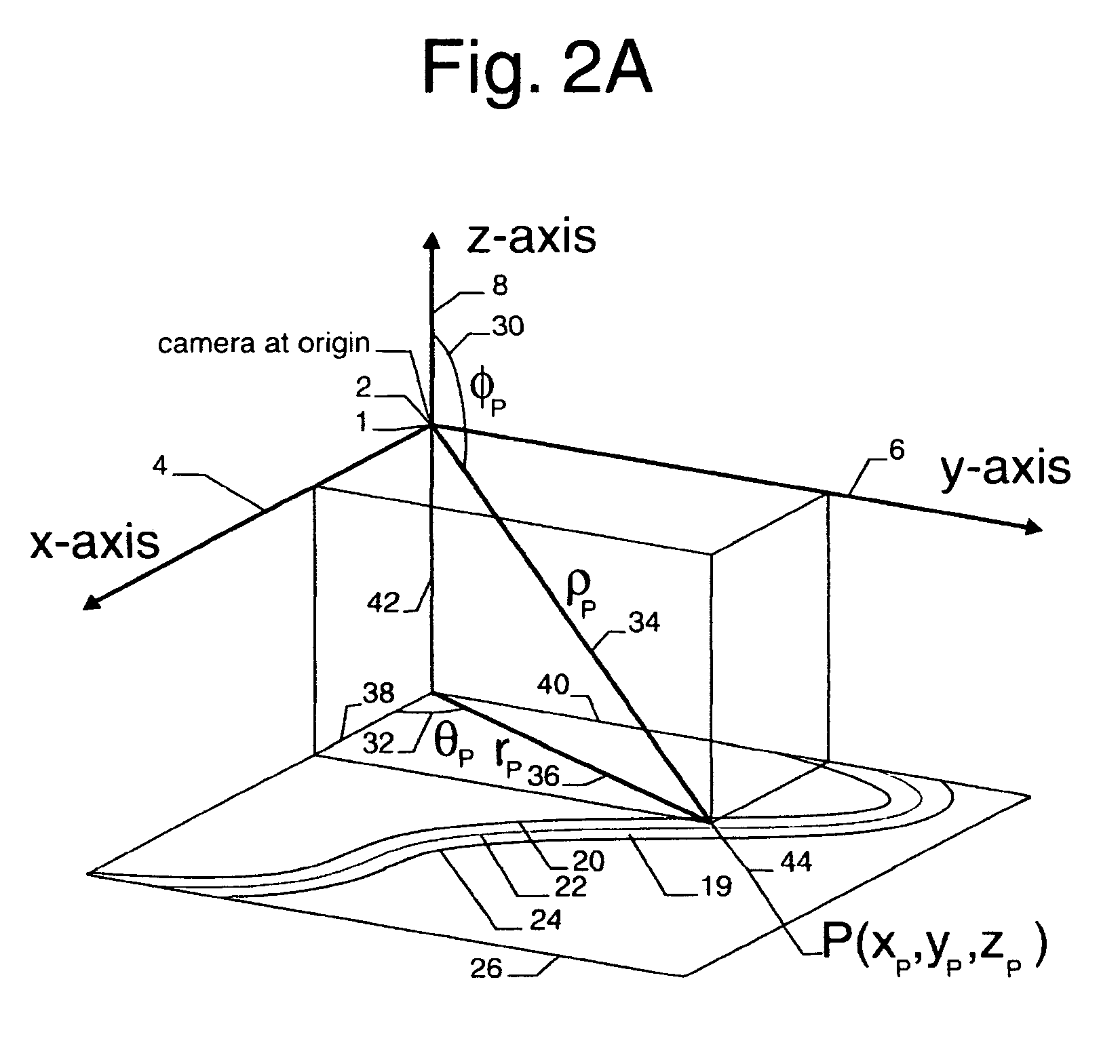
[0029]A preferred embodiment of the present invention is a three-dimensional vehicle velocity vector analysis system. According to this three-dimensional vehicle velocity vector analysis system, a single camera 2 is mounted above a roadway system and observes the roadway system in camera 2′s field of view. The roadway system may comprise individual roads 19 which may head in different directions, have different elevations, have elevations, which change with distance, and have curves, which change the direction of the roads. Vehicles 18 traveling on the individual roads 19 may travel in different directions.

[0030]The single camera 2 and a data storage system (not shown) record an image sequence of the vehicles traveling on individual roads 19. Each image of the image sequence is called a frame, the t...


PUM


Abstract

A method and an apparatus is provided for determining the velocity vector, speed, and direction of moving vehicles traveling on roadways which change elevation and have curves. A camera mounted above a roadway observes at least one vehicles traveling in different directions on different roads. Each pixel in the two-dimensional optical image is mapped into a three-dimensional real world location to enable the moving vehicles to be analyzed in the three-dimensional real world as they travel on roads, which may change elevation and may have curves. The estimated vehicle velocities may be displayed on an image near the moving vehicle. Individual images with vehicle velocities may be posted on an Internet site. The sequence of optical images, or streaming video, with the displayed vehicle velocities may also be used for television news programs that show traffic moving on the roadways.

Description

CROSS-REFERENCE TO RELATED APPLICATIONS[0001]The present application claims priority from Provisional U.S. patent application Ser. No. 60 / 676,676 filed on May 1, 2005, and incorporated herein by reference.FIELD OF THE INVENTION[0002]The present invention relates to measuring the position, velocity vector, speed, and direction of moving vehicles. Specifically the present invention analyzes sequences of two-dimensional optical images to detect multiple vehicles on non-level and curved roads and estimates the three-dimensional real-world position, velocity vector, speed, and direction of moving vehicles.BACKGROUND OF THE INVENTION[0003]Thousands of Americans die and millions of Americans are injured each year in automobile accidents that involve at least one vehicle traveling with excessive speed. There is no doubt that lives would be saved and fewer accidents would occur if Americans drove at or below the speed limit.[0004]Currently, there are three technologies commonly used to measu...

Claims


Application Information

Patent Timeline
IPC IPC(8): G08G1/00G06T15/00G06K9/20
CPCG06T7/2053G06T17/00G08G1/056G08G1/0104G06T2207/30236G06T2207/10016G06T7/254
Inventor WILLIAMS, CHRISTOPHER REED
Owner WILLIAMS CHRISTOPHER REED
Why Eureka
Try Eureka