Cooled turbine stator vane

a technology of stator vane and turbine, which is applied in the direction of stators, machines/engines, liquid fuel engines, etc., can solve the problems of increasing the pressure drop across the impingement hole, not providing adequate impingement cooling to the inner wall of the leading edge, and unable to meet the needs of impingement cooling, etc., to achieve the effect of increasing the gas flow temperatur

Inactive Publication Date: 2011-04-12
FLORIDA TURBINE TECH
View PDF26 Cites 62 Cited by
  • Summary
  • Abstract
  • Description
  • Claims
  • Application Information

AI Technical Summary

Benefits of technology

[0017]A first stage turbine stator vane used in an industrial gas turbine engine, the vane having an outer endwall and an inner endwall with the airfoil extending between the two endwalls. A showerhead arrangement of film cooling holes is located along the leading edge region, and a row of exit cooling air slots is located along the trailing edge of the airfoil. A slanted rib extends from the outer endwall to the inner endwall and separates the vane into a forward cavity and an aft cavity. A leading edge impingement tube is secured within the forward cavity to provide impingement cooling to the leading edge walls of the...

Problems solved by technology

Above this percentage and the impingement holes could become closed from impurities in the cooling air and not provide adequate impingement cooling to the inner wall of the leading edge.
Also, when a number of impingement cooling holes become closed, the pressure drop across the impingement holes bec...

Method used


Image

  • Cooled turbine stator vane
  • Cooled turbine stator vane
  • Cooled turbine stator vane

Examples


Embodiment Construction

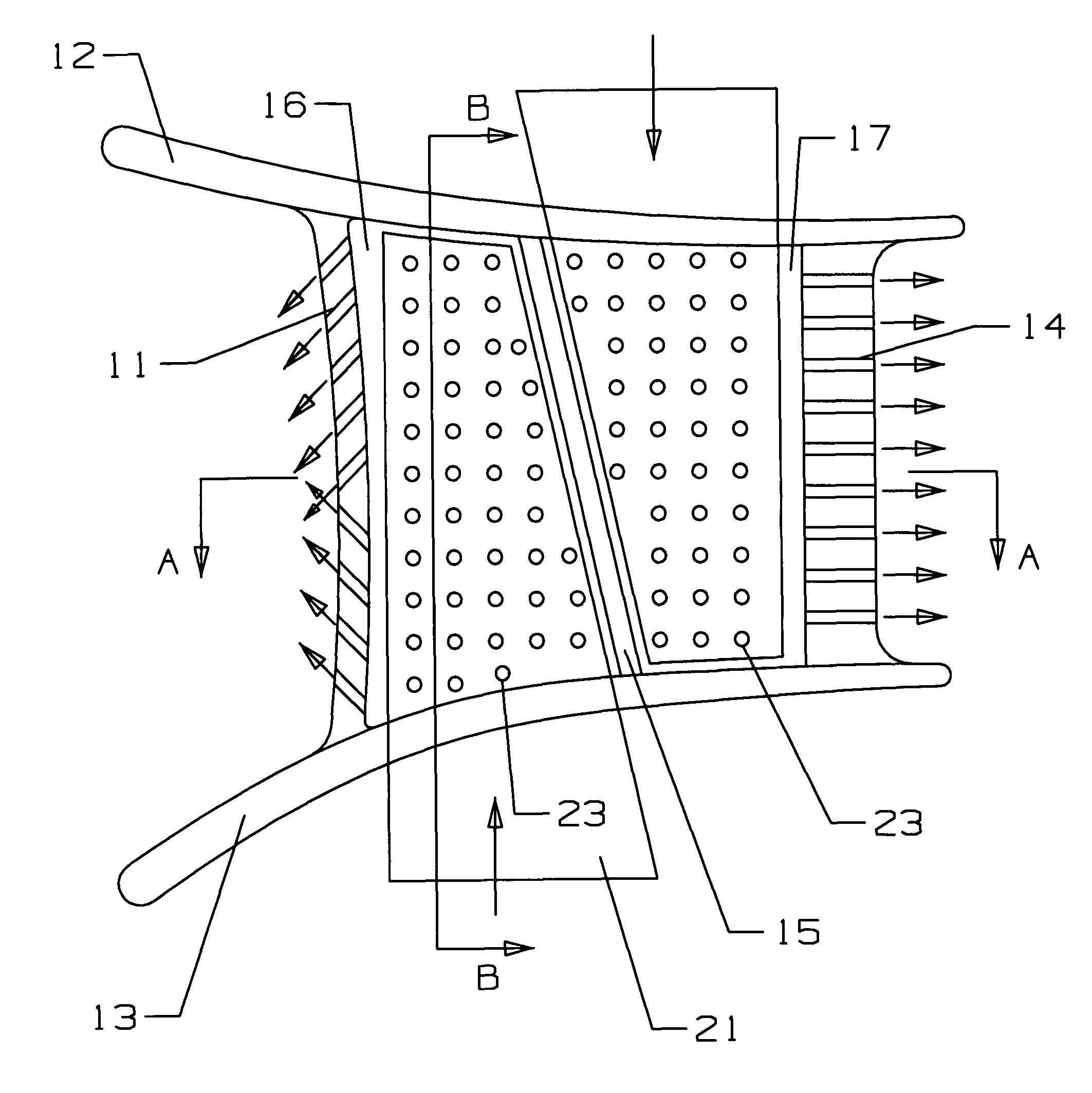
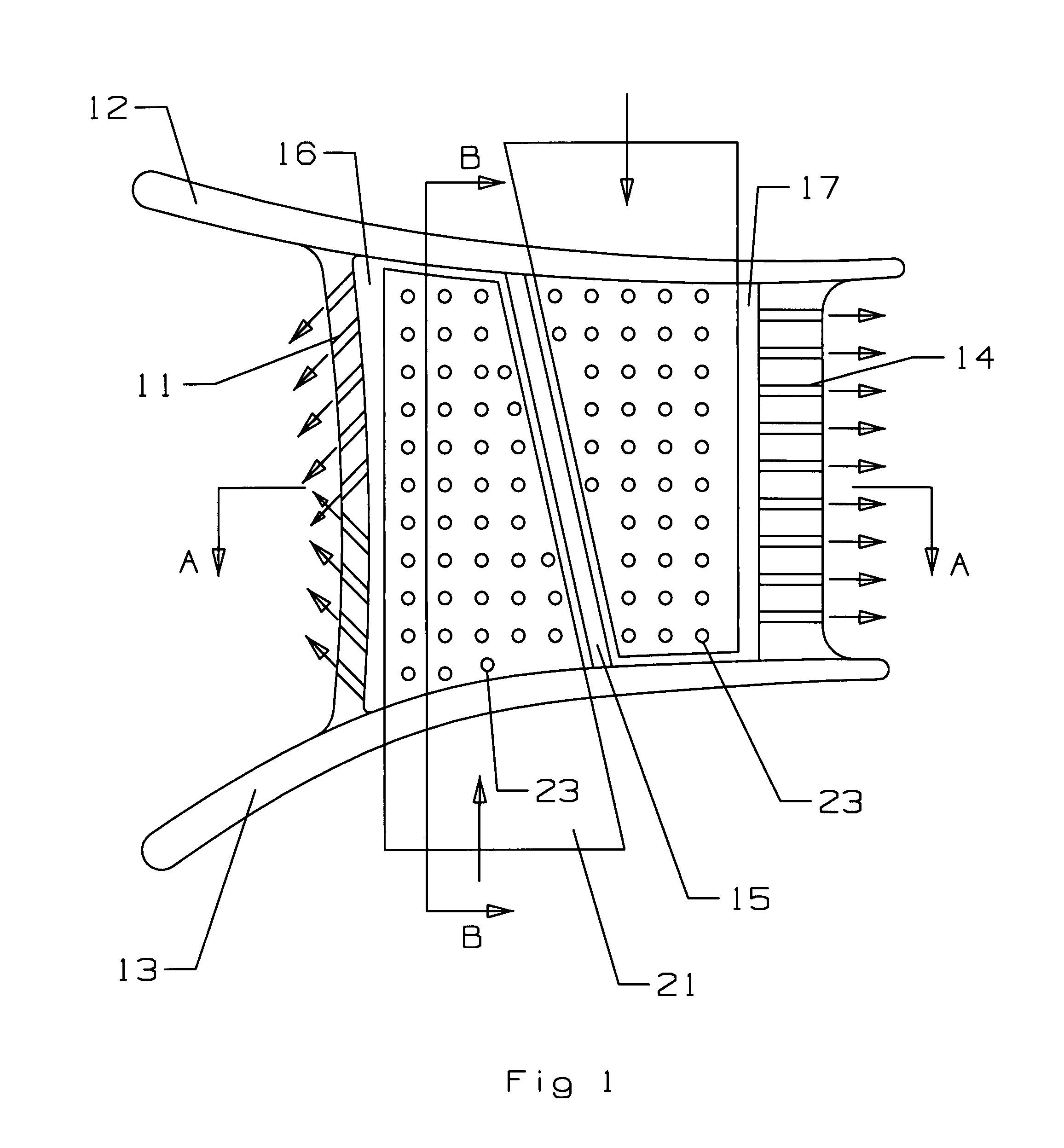
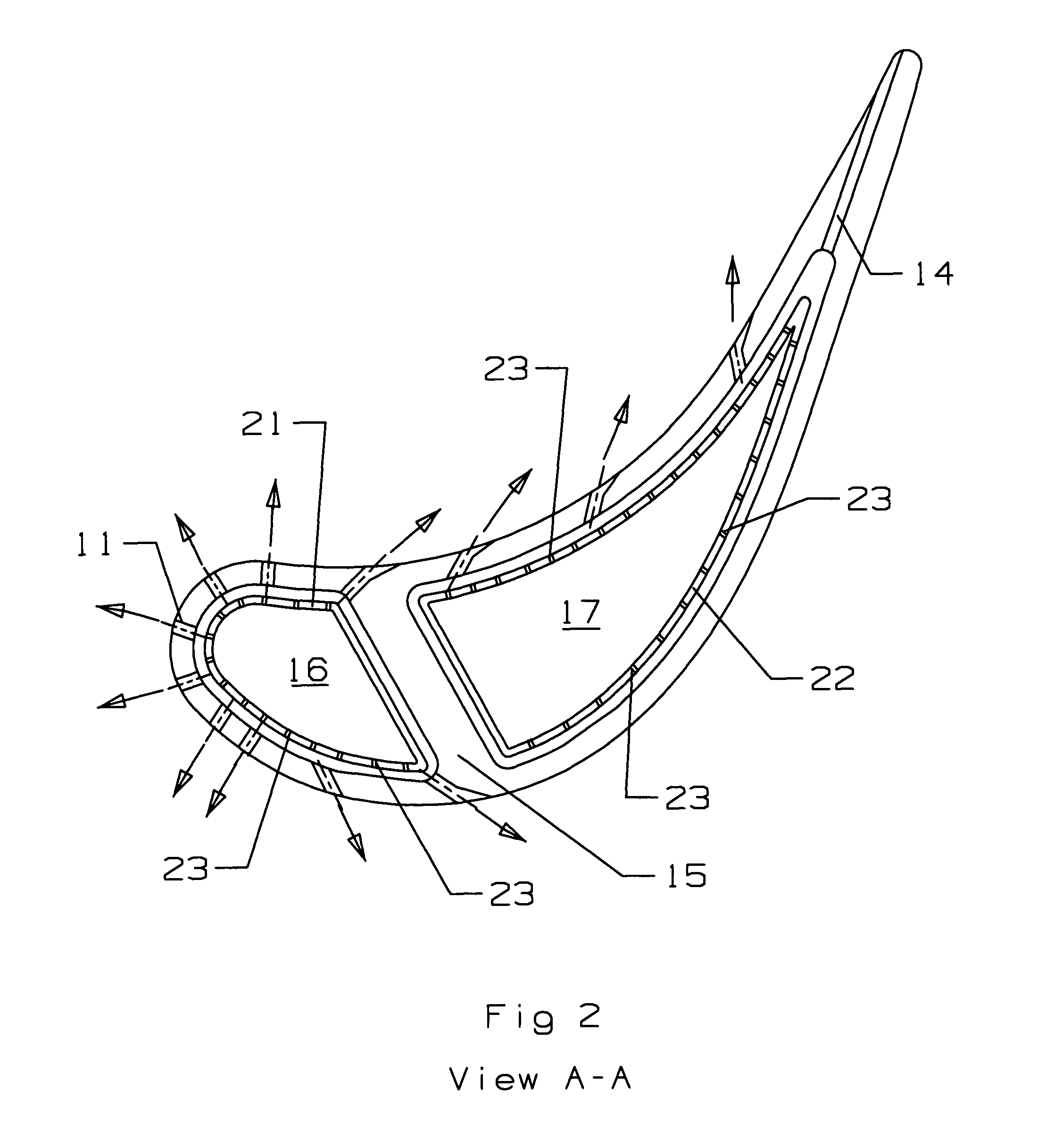
[0024]The turbine stator vane of the present invention is intended for use as the first stage vane in an industrial gas turbine engine. However, the concepts of the present invention could be useful for other stages of vanes or for vanes in other types of gas turbine engines such as those that power an aircraft. FIG. 1 shows a side view through a cross section of the stator vane. The vane includes a leading edge showerhead 11 with film cooling holes on the upper half of the leading edge directing cooling air toward the lower half of the leading edge, and film cooling holes on the lower half directing cooling air toward the upper half of the leading edge. An inner diameter endwall 12 and an outer diameter endwall 13 define a hot gas flow path through the airfoil portion of the vane. A trailing edge includes a row of exit cooling air slots 14 to discharge cooling air out through the trailing edge region of the vane. A slanted rib 15 extends from a forward position on the outer diamete...


PUM


Abstract

A first stage turbine stator vane used in an industrial gas turbine engine, the vane having an outer endwall and an inner endwall with the airfoil extending between the two endwalls. A showerhead arrangement of film cooling holes is located along the leading edge region, and a row of exit cooling air slots is located along the trailing edge of the airfoil. A slanted rib extends from the outer endwall to the inner endwall and separates the vane into a forward cavity and an aft cavity. A leading edge impingement tube is secured within the forward cavity to provide impingement cooling to the leading edge walls of the airfoil. The leading edge impingement tube includes a cooling air inlet section extending out from the inner endwall so that a vena contractor forms in the tube entrance before the impingement holes begin. The leading edge impingement tube narrows in the cooling air flow direction. The trailing edge impingement tube has similar construction but has the cooling air inlet extending out from the outer endwall. With this design, the first stage vane can use both impingement cooling of the leading edge region and showerhead film cooling of the leading edge airfoil surface to allow for a higher gas flow temperature across the vane.

Description

BACKGROUND OF THE INVENTION[0001]1. Field of the Invention[0002]The present invention relates generally to a gas turbine engine, and more specifically to an air cooled stator vane with impingement and film cooling.[0003]2. Description of the Related Art Including Information Disclosed Under 37 CFR 1.97 and 1.98[0004]In a gas turbine engine, air is pressurized in a compressor and mixed with fuel and ignited in a combustor for generating hot combustion gases. The gases are discharged through a first stage high pressure turbine nozzle having stator vanes which direct the gases toward a row of turbine rotor blades extending radially outwardly from a supporting disk.[0005]The turbine blades extract energy from the combustion gases and power the compressor. The gases are then channeled to a low pressure turbine typically having several stages of nozzle vanes and rotor blades which extract additional energy from the gases for producing output work such as powering a fan in a turbofan aircr...

Claims


Application Information

Patent Timeline
IPC IPC(8): F02C7/12
CPCF01D5/186F01D9/041Y02T50/676F05B2240/801F05D2240/81Y02T50/60
Inventor LIANG, GEORGE
Owner FLORIDA TURBINE TECH
Why Eureka
Try Eureka