Oxygen supply humidification system

a technology of oxygen supply and humidification system, which is applied in the direction of heating types, lighting and heating apparatus, and separation processes, etc., can solve the problems of affecting the efficiency of known devices, affecting the effectiveness of known devices, etc., to achieve the effect of maintaining the effectiveness of devices and being easy to carry by very frail patients

Inactive Publication Date: 2011-04-19
BERTOLI CHARLES J
View PDF16 Cites 12 Cited by
  • Summary
  • Abstract
  • Description
  • Claims
  • Application Information

AI Technical Summary

Benefits of technology

[0017]According to a preferred embodiment of the invention, the hollow water reservoir will include sidewalls that gradually taper from the upper cross sectional area to the lower cross sectional area. Still further, it is further contemplated that the hollow water reservoir may include spiral projections that extend into the hollow water reservoir. The spiral projections may be simply molded into the hollow water reservoir, and force oxygen bubbles formed through the diffuser to follow the projections on their way up through the water in the hollow water reservoir, and thus causing the bubbles to remain in contact with the water for a longer period of time, allowing a greater amount of moisture to mix with the oxygen.
[0018]The reduction in the cross sectional areas, from a larger upper cross sectional area to a smaller lower cross sectional area, allows water in the hollow water reservoir to be funneled down to where the diffuser is positioned, and held up against the diffuser. This arrangement allows the diffuser to be completely immersed in water while using a very small amount of water. As explained above, the ability to maintain the device's effectiveness with a very small volume of water results in a very lightweight system that can be easily carried by very frail patients.

Problems solved by technology

A significant problem associated with oxygen therapy is that the oxygen to be administered to the patient is dispensed in a substantially pure form from a cylinder containing the oxygen, a source of oxygen in a liquid state, or from an oxygen concentration system that delivers the oxygen to the patient through a hose that is attached to a breathing mask or a cannula that delivers the gas to the nasal passages.
This dryness leads to the drying out of the patient's nasal passages, which eventually leads to chapped nasal tissue and bleeding through cracking of the chapped tissue.
However, known devices suffer from a lack of efficiency due to the fact that they typically expose the oxygen by simply placing the end of a tube or pipe in a water bath.
This approach provides very little control over the size of the bubbles being delivered from the end of the tube, and thus provides little control over the amount of humidification of the oxygen or gas being delivered to the patient.
A significant limitation to this approach is that the diffuser must be kept immersed in water, and thus a significant amount of water must be kept in the humidifier in order to ensure proper function of the diffuser.
Many known devices simply provide a fixed, predetermined, amount of humidification, and do not allow for the patient to control the amount of humidification achieved by the device.

Method used


Image

  • Oxygen supply humidification system
  • Oxygen supply humidification system
  • Oxygen supply humidification system

Examples


Embodiment Construction

[0033]While the invention will be described and disclosed here in connection with certain preferred embodiments, the description is not intended to limit the invention to the specific embodiments shown and described here, but rather the invention is intended to cover all alternative embodiments and modifications that fall within the spirit and scope of the invention as defined by the claims included herein as well as any equivalents of the disclosed and claimed invention.

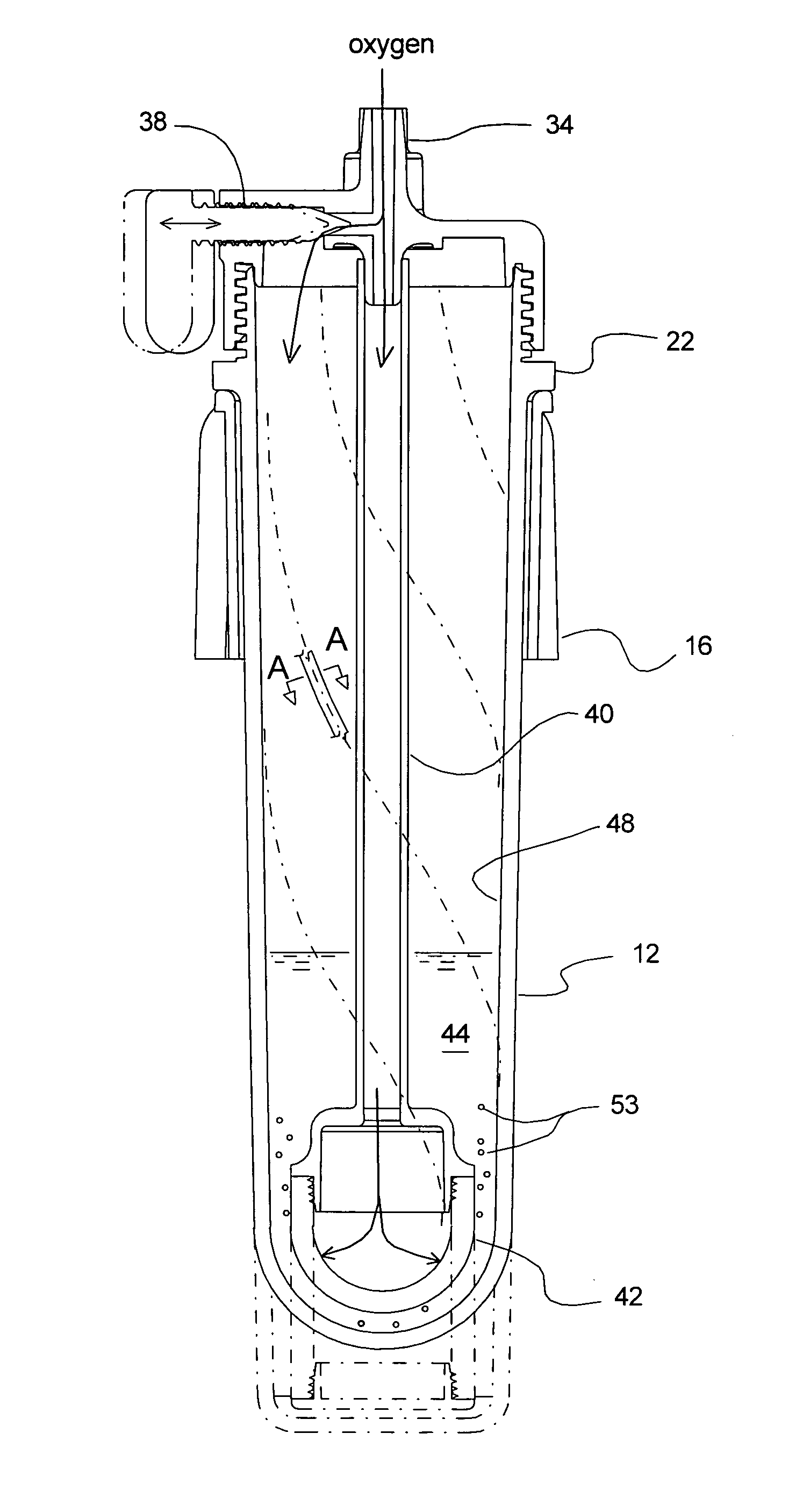
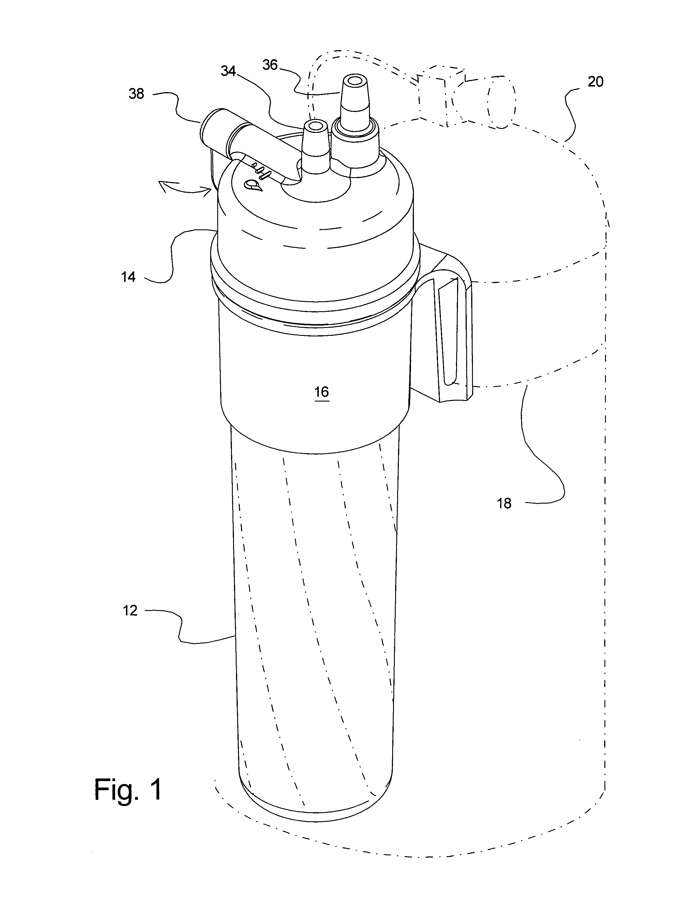
[0034]Turning now to FIG. 1 where a preferred example of a perspective view of an oxygen therapy humidification device 10 that includes inventive structure taught here is illustrated, it will be understood that a preferred example of the oxygen therapy humidification device 10 is designed such that it may be carried by a patient, but as will be discussed below it is also contemplated that it may be used in conjunction with stationary devices, such as fixed oxygen therapy systems that are found in hospitals, assisted...


PUM

PropertyMeasurementUnit
cross-sectional areaaaaaaaaaaa
areaaaaaaaaaaa
temperatureaaaaaaaaaa

Abstract

An oxygen therapy humidification device is disclosed. The humidification device includes a hollow water reservoir that includes an upper end that has an upper cross-sectional area and a lower end that has a lower cross-sectional area. The lower cross-sectional area is smaller than the upper cross-sectional area. The device also includes an oxygen inlet and an oxygen outlet, both of which are positioned at the upper end of the hollow water reservoir and provide fluid communication to and from the hollow water reservoir. The oxygen inlet includes a bypass valve that is connected to a duct that extends from the oxygen inlet to a diffuser that is positioned at the lower end of the hollow water reservoir. The bypass valve allows the user to control the proportion of water vapor or humidity delivered to oxygen that is passed through the device, with the oxygen entering through the inlet and leaving through the outlet at the desired humidity level.

Description

BACKGROUND OF THE INVENTION[0001](a) Field of the Invention[0002]This application relates to a system for humidifying oxygen to be supplied through an oxygen therapy device such as the type to be carried by individuals who are required to breathe oxygen-enriched air under medical supervision. More particularly, but not by way of limitation, this application relates to a system that includes a reservoir and a diffuser for enhancing humidification of oxygen being through a water reservoir for humidification.[0003](b) Discussion of Known Art[0004]The need to humidify gasses being delivered to a patient though breathing devices, such as face masks or tubes that deliver the gas through nasal passages or other passages that lead to a patient's lungs has long been recognized. The humidify these gasses has led to the development of various devices that assist the gas in becoming humidified. As is well known, the ability of a fluid in a gaseous state, such as oxygen or air at room temperatur...

Claims


Application Information

Patent Timeline
Patent Type & Authority Patents(United States)
IPC IPC(8): B01F3/04
CPCF24F6/00F24F2003/1692F24F8/60
Inventor BERTOLI, CHARLES J.
Owner BERTOLI CHARLES J
Why Eureka
Try Eureka