Air cleaner element

a technology of air cleaner and element, applied in the direction of separation process, auxillary pretreatment, filtration separation, etc., can solve the problems of reducing the flow resistance, complicating the manufacture of the element, and affecting the flow resistance, so as to achieve high filtering performance

Inactive Publication Date: 2011-04-19
TOYOTA BOSHOKU KK
View PDF11 Cites 24 Cited by
  • Summary
  • Abstract
  • Description
  • Claims
  • Application Information

AI Technical Summary

Benefits of technology

[0009]Accordingly, it is an objective of the present invention to provide a simply configured air cleaner element that functions as a handle when an element body is removed or mounted, and prevents a large sized foreign matter from entering the element body while maintaining high filtering performance.

Problems solved by technology

However, the configurations of these prior arts have the following problems.
This disadvantageously complicates the manufacture of the element.
This decreases the amount of air flow that passes through the air cleaner, thus increasing the flow resistance of the air flow and lowering filtering performance of the air cleaner.
This complicates the configuration of the air cleaner and increases the number of the components.
In the third prior art, the pre-filter may be clogged quickly.

Method used


Image

  • Air cleaner element
  • Air cleaner element
  • Air cleaner element

Examples


first embodiment

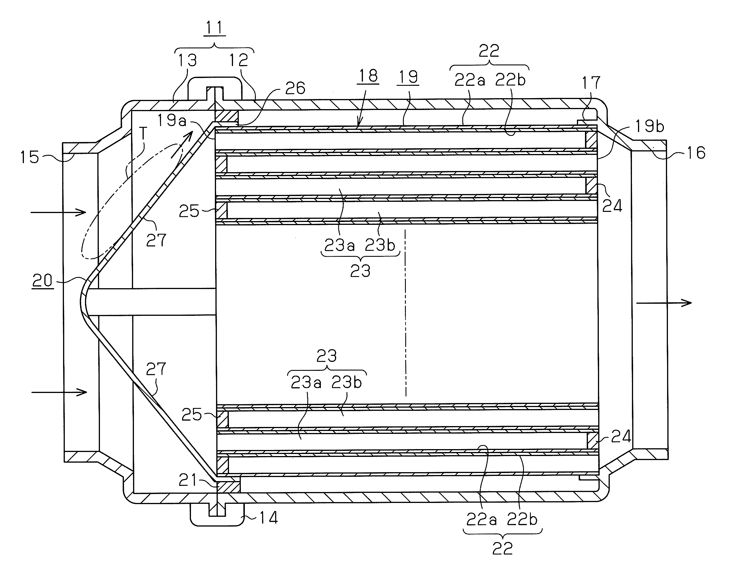
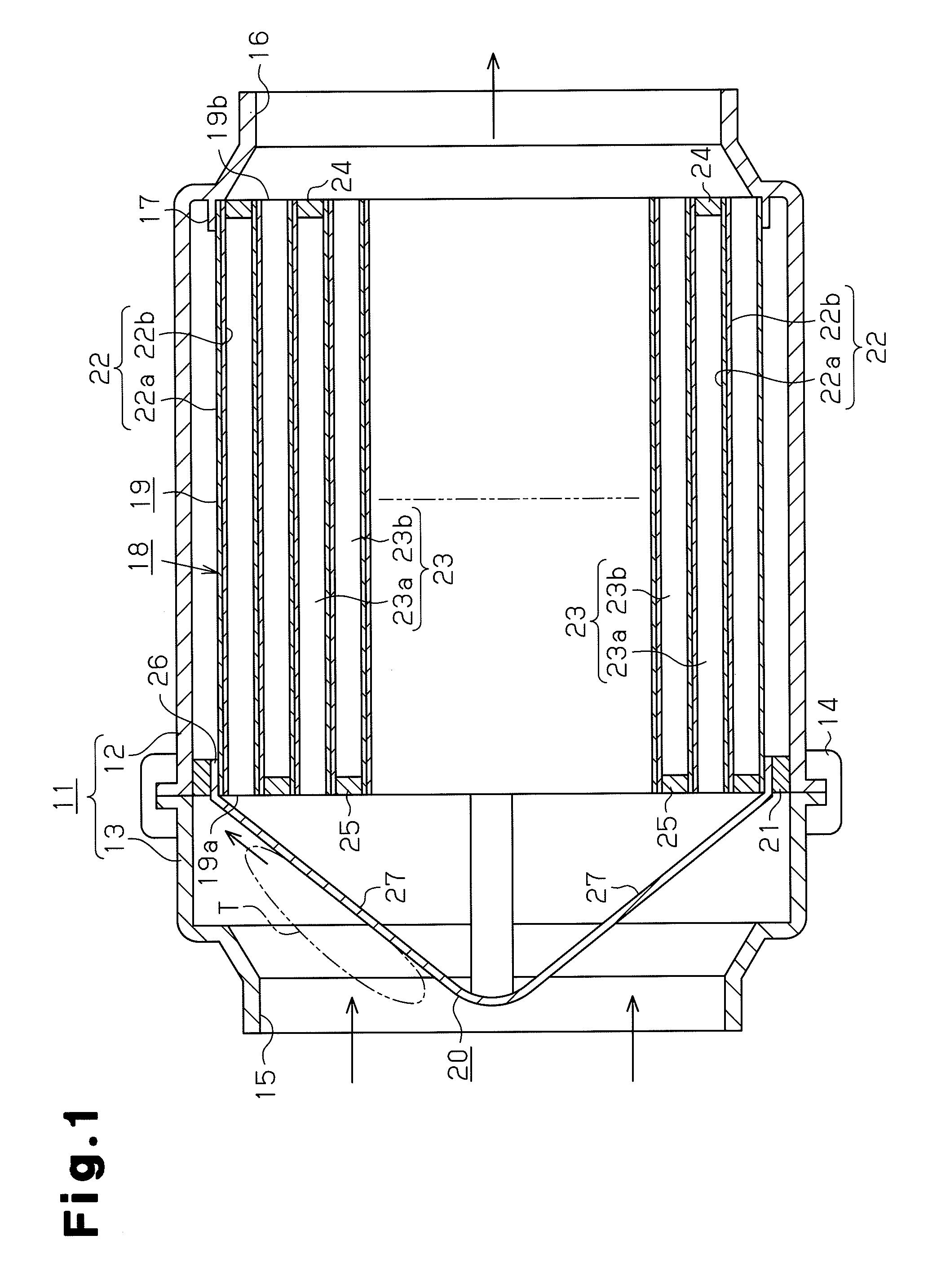
[0020]An air cleaner element according to a first embodiment of the present invention will now be described with reference to FIGS. 1 to 3.

[0021]As shown in FIG. 1, a casing 11 of the air cleaner includes a cylindrical casing body 12 having a large-diameter opening end and a cover 13, which is removably secured to the opening end of the casing body 12 by a clamp 14. An air inlet port 15, which communicates with the outside air, is defined in the circumferential wall of the cover 13 with the walls of the air inlet port 15 projected from the circumferential wall. An air outlet port 16, which is connected to an intake system of an engine, is defined by the circumferential wall of the casing body 12 at a position opposite to the air inlet port 15, with the walls of the air outlet port 16 projecting from the circumferential wall. A cylindrical holder 17 is formed on and projected from the inner surface of the circumferential wall of the casing body 12.

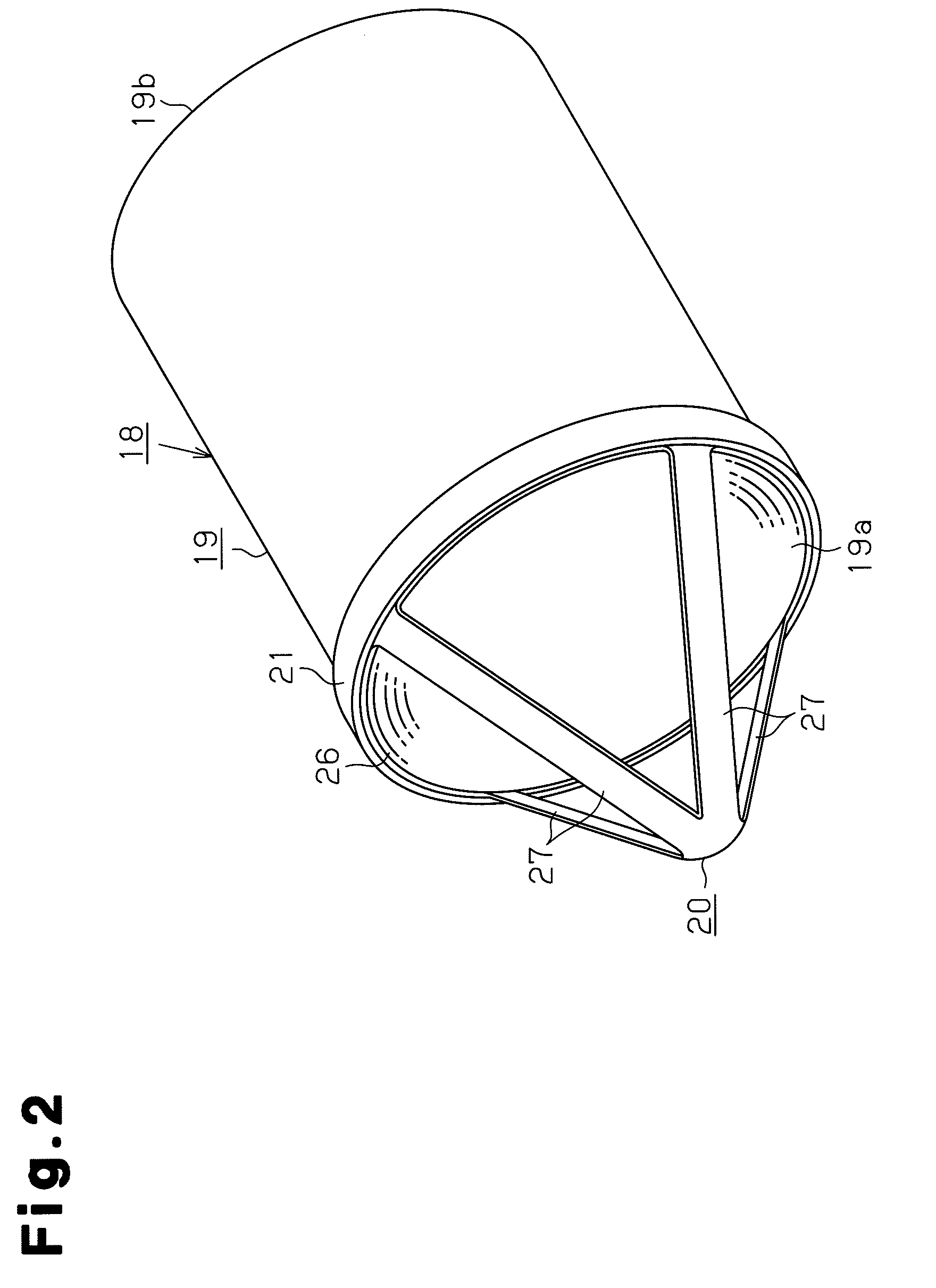
[0022]The air cleaner element 18 is ...

second embodiment

[0035]A second embodiment of the present invention will hereafter be explained mainly on the difference between the second embodiment and the first embodiment.

[0036]As illustrated in FIG. 4, a ring 30 is formed at the distal end of the guard member 20 and the distal end of each guard portion 27 is connected to the ring 30. The outer diameter of the ring 30 is smaller than the outer diameter of the first end surface 19a of the element body 19.

[0037]Accordingly, the air cleaner element of the second embodiment has advantages substantially equivalent to those of the first embodiment. The second embodiment additionally has the following advantage.

[0038](4) The connecting portion of the distal ends of the guard portions 27 is the ring 30. The air passes through the space surrounded by the ring 30. This reduces the flow resistance of the air at the connecting portion of the distal ends of the guard portions 27.

third embodiment

[0039]As shown in FIG. 5, an air cleaner element according to a third embodiment of the present invention includes a plurality of leg portions 26, which are formed integrally with the proximal portions of the corresponding guard portions 27 and provided separately from one another, without being connected together in an annular shape. The seal member 21 is secured to the outer circumferences of the leg portions 26 in such a manner that the leg portions 26 are connected together.

[0040]The third embodiment has the following advantage.

[0041](5) The leg portions 26 of the guard member 20 are provided as separate components without being connected together. This configuration reduces the weight of the guard member 20.


PUM

PropertyMeasurementUnit
circumferenceaaaaaaaaaa
outer diameteraaaaaaaaaa
conical shapeaaaaaaaaaa

Abstract

An air cleaner element includes an element body, which filters an air flow, and a guard member secured to the element body. The air flow is introduced into the element body through a first end surface of the element body. The air flow is then filtered and sent out from a second end surface. The guard member has a leg portion, which is secured to an outer circumferential portion of the first end surface of the element body. The guard member projects toward the upstream side of the air flow and includes guard portions which are connected together at the distal ends of the guard portions. The guard portions function as a handle when the element body is removed or installed and as a blockage portion that prevents large-sized foreign matter from entering the element body.

Description

BACKGROUND OF THE INVENTION[0001]The present invention relates to an air cleaner element that filters air drawn to, for example, an internal combustion engine.[0002]Conventionally, this type of air cleaner element includes a honeycomb-shaped filter element, as disclosed in, for example, Japanese National Phase Patent Publication No. 2003-514178 (first prior art), Japanese Laid-Open Utility Model Publication No. 2-127766 (second prior art), and Japanese Laid-Open Utility Model Publication No. 2-129231 (third prior art). In the element of these prior arts, an element body is removably mounted in a casing of an air cleaner through a seal member. An air flow is introduced from a first end surface of the element body into the element body. The air flow is then filtered and sent out from a second end surface of the element body.[0003]In the first prior art, a core member is embedded in the center of the element body. A handle is formed at an end of the core member and projects from one of...

Claims


Application Information

Patent Timeline
Patent Type & Authority Patents(United States)
IPC IPC(8): B01D50/00
CPCB01D46/0084B01D46/2422B01D46/527B01D2046/2492B01D46/2466B01D46/2451B01D46/2486B01D46/2482
Inventor SANAMI, YOSHIHISA
Owner TOYOTA BOSHOKU KK
Why Eureka
Try Eureka