Organic electroluminescent display with improved barrier structure

a technology of electroluminescent display and barrier structure, which is applied in the manufacture of luminescnet screens, electric discharge tubes/lamps, discharge tubes, etc., can solve the problems of shortening the life of the device, affecting the waterproof ability of the device, so as to reduce the oxidation of the electrodes, prevent moisture infiltration, and reduce fabrication costs

Active Publication Date: 2011-04-19
INNOLUX CORP
View PDF5 Cites 10 Cited by
  • Summary
  • Abstract
  • Description
  • Claims
  • Application Information

AI Technical Summary

Benefits of technology

[0011]The organic electroluminescent display device effectively prevents infiltration of moisture into the electroluminescent unit for reducing oxidation of electrodes. Because the first protective layer comprises inorganic material, the second protective layer comprises organic material and the third protective layer comprises inorganic material are formed on the electroluminescent unit moisture infiltration is prevented. Additionally, stress between the first protective layer comprising inorganic material and the third protective layer comprising inorganic material is relieved by the second protective layer comprising organic material formed therebetween. Further the second protective layer is only formed in a recess over the electroluminescent unit, thus, fabrication cost is reduced. The second protective layer formed in the recess over the electroluminescent unit provides improved organic electroluminescent display device waterproof capability is without increasing total thickness. Accordingly, life of the organic electroluminescent display device is increased.

Problems solved by technology

Organic electroluminescent display devices are however easily affected by moisture, such as oxidation of electrodes and components, shortening life.
The waterproof ability of the device suffers due to the use of only a single protective layer.

Method used


Image

  • Organic electroluminescent display with improved barrier structure
  • Organic electroluminescent display with improved barrier structure
  • Organic electroluminescent display with improved barrier structure

Examples


first embodiment

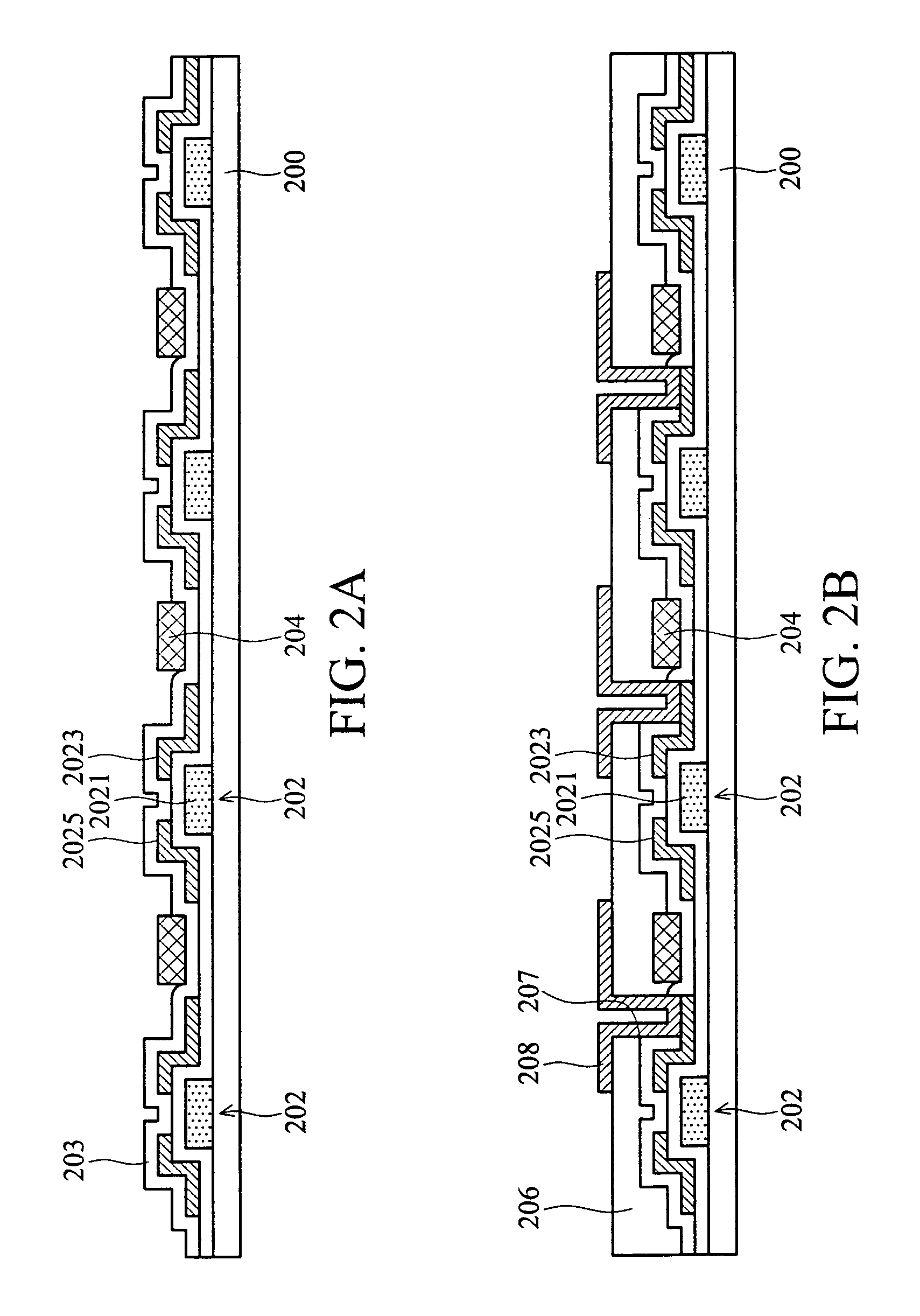
[0019]FIG. 2A through FIG. 2H, show cross-sectional views of forming an organic electroluminescent display device according to the invention. In this embodiment, a color filter and thin film transistor serving as a switch may be disposed on the same substrate in the organic electroluminescent display device. That is, the color filter may be formed on the substrate on which the thin film transistor is formed.

[0020]As shown in FIG. 2A, a color filter 204 is formed on a first substrate 200 having a plurality of thin film transistors (TFTs) 202 formed thereon. The first substrate 200 is transparent material, such as, glass or plastic. The flexible transparent material may also be used in first substrate 200.

[0021]The thin film transistor 202, serving as a switch, includes a gate electrode 2021, a source 2025 and drain 2023, in which the gate electrode 2021 is formed on the first substrate 200 followed by formation of the source 2025 and drain 2023 thereon. The gate electrode, source and...

second embodiment

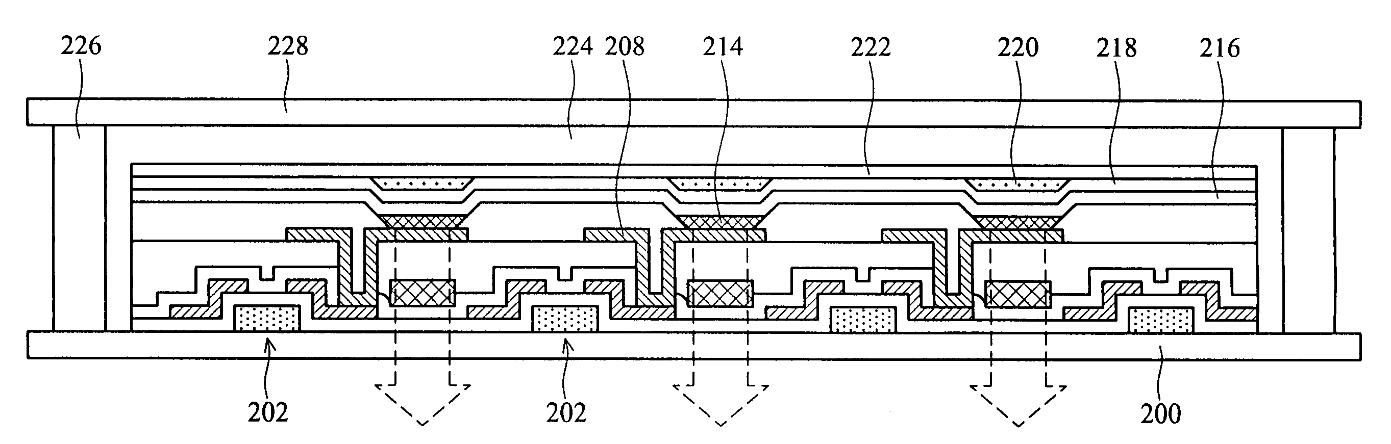
[0054]The organic electroluminescent display device of the invention effectively prevents oxidation of electrodes by infiltration of moisture into the electroluminescent unit. Because the first protective layer comprising inorganic material, the second protective layer comprising organic material and the third protective layer comprising inorganic material are formed on the electroluminescent unit to prevent moisture infiltration. Additionally, a stress between the first protective layer comprising inorganic material and the third protective layer comprising inorganic material is reduced by forming the second protective layer comprising organic material therebetween. Furthermore, the second protective layer is only formed in the recess over the electroluminescent unit, thus, fabrication cost is reduced. Furthermore, waterproof ability of the organic electroluminescent display device is enhanced without increasing thickness of the organic electroluminescent display device because th...

third embodiment

[0058]A third protective layer 422 is then formed on the second protective layer 420 and in contact with the first protective layer 418 after the second protective layer 420 is formed. Finally, a second substrate 428 is sealed to the first substrate 400 by a sealant 426. A buffer layer 424 is filled between the first substrate 400 and second substrate 428, to complete an organic electroluminescent display device according to the invention, as shown in FIG. 4.

[0059]Note that color filter and shielding layer is not necessarily formed on the second substrate, thus, steps of fabrication and cost of material utilized are reduced. A stress between the first protective layer comprising an inorganic material and third protective layer comprising an inorganic material is reduced because the second protective layer comprises an organic photoresist. Note that the second protective layer in first embodiment may be a material of organic color photoresist function as protective layer and color fi...


PUM


Abstract

An organic electroluminescent display device and fabrication method thereof is provided. The device includes a first substrate having at least one thin film transistor; an electroluminescent unit formed on the first substrate and electrically connect to the thin film transistor; a first protective layer formed on the electroluminescent unit; a second protective layer formed on the first protective layer; and a third protective layer formed on the second protective layer and in contact with the first protective layer. The device further comprises a second substrate sealed to the first substrate to form the electroluminescent unit between the first substrate and second substrate. In the device, the first protective layer comprising inorganic material, the second protective layer comprising organic material and the third protective layer comprising inorganic material are formed on the electroluminescent unit to reduce oxidation of electrodes by preventing infiltration of moisture.

Description

BACKGROUND OF THE INVENTION[0001]1. Field of the Invention[0002]The invention relates to organic electroluminescent display devices, and more particularly to an organic electroluminescent display device having improved waterproof capabilities and a fabrication method thereof.[0003]2. Description of the Related Art[0004]Organic electroluminescent display devices possess advantages of improved color, viewing angle, brightness and reduced size when compared with conventional displays, such as cathode ray tube (CRT) displays or liquid crystal displays (LCD). Thus, demand for organic electroluminescent display devices is increasing. Organic electroluminescent display devices are however easily affected by moisture, such as oxidation of electrodes and components, shortening life. Thus, encapsulated structures and fabrication of organic electroluminescent display devices is important.[0005]FIG. 1 shows a conventional organic electroluminescent display device. A first electrode 12 is formed...

Claims


Application Information

Patent Timeline
Patent Type & Authority Patents(United States)
IPC IPC(8): H01J1/62H01J63/04H05B33/00
CPCH01L51/5237H01L27/3244H10K59/38H10K59/122H10K2102/3026H10K59/8731H10K59/80518H10K50/844H10K50/818
Inventor RYUJI, NISHIKAWAHSU, HSIANG-LUN
Owner INNOLUX CORP
Why Eureka
Try Eureka