Sliding window block codes for cross-packet coding

a window block and cross-packet technology, applied in the field of network coding techniques, can solve the problems of df decoder, unable to guarantee the recovery of any particular piece of information, and packet source latency, and achieve the effect of reducing transmission overhead and less decoding latency

Active Publication Date: 2011-04-19
ROCKWELL COLLINS INC
View PDF10 Cites 23 Cited by
  • Summary
  • Abstract
  • Description
  • Claims
  • Application Information

AI Technical Summary

Benefits of technology

[0028]This invention allows a receiver to recover a defined number of lost packets without requiring additional packet transmissions, which reduces transmission overhead compared to standard ARQ approaches. The invention provides a mechanism to transmit additional packets when necessary, where such packets can be used to recover previous lost packets by multiple receivers. The invention does not require encoding latency and requires less decoding latency than other approaches, such as digital fountain codes.

Problems solved by technology

This leads to latency at the source while packets accumulate.
The DF decoder, on the other hand, does not guarantee recovery of any particular piece of information until the entire message has been recovered.
Because erasures do not provide soft decisions, however, the advantages of conventional trellis-based codes are minimized.
These codes introduce latency, however, because an entire message block must be accumulated before encoding begins.
These codes do not, however, produce parity symbols suitable for multicast retransmissions.
These types of codes are systematic sliding window codes with low latency but may be complex to implement.
Conventional convolutional decoders, however, can have large decoding delays.
If different receivers have lost different packets, however, different punctured symbols may be required to correct the different error paths in the decoder trellis.
Maintaining the decoder trellis may also require significant processing and memory.
The structure of convolutional codes is not as compatible with the desired application as the structure of block codes.
Turbo decoding also requires significant processing.

Method used


Image

  • Sliding window block codes for cross-packet coding
  • Sliding window block codes for cross-packet coding
  • Sliding window block codes for cross-packet coding

Examples


Embodiment Construction

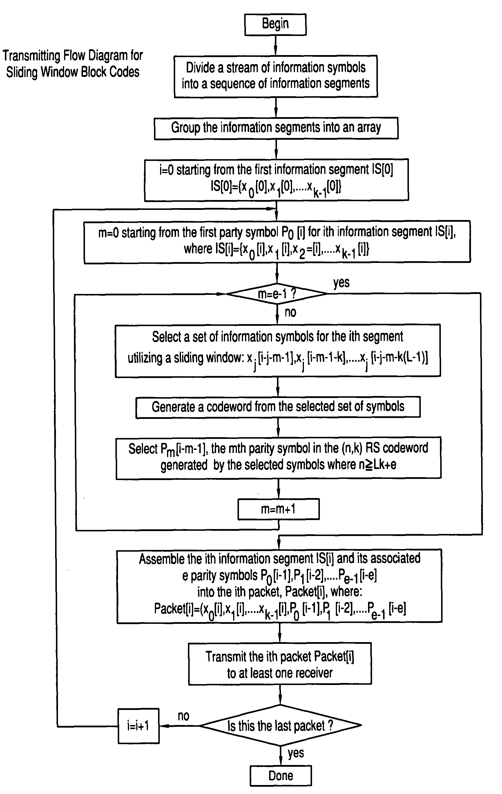
[0042]Referring now to FIG. 1, a preferred embodiment of a method for communicating information symbols in a digital communications system in accordance with the principles of the present invention is illustrated. First of all, a transmitter divides a stream of information symbols into a sequence of information segments, each of which contains k symbols. The ith information segment is denoted as IS[i], and the k symbols in the ith information segment are denoted as x0[i], x1[i], . . . , xk−1[i], where IS[i]={x0[i], x1[i], . . . , xk−1[i]}

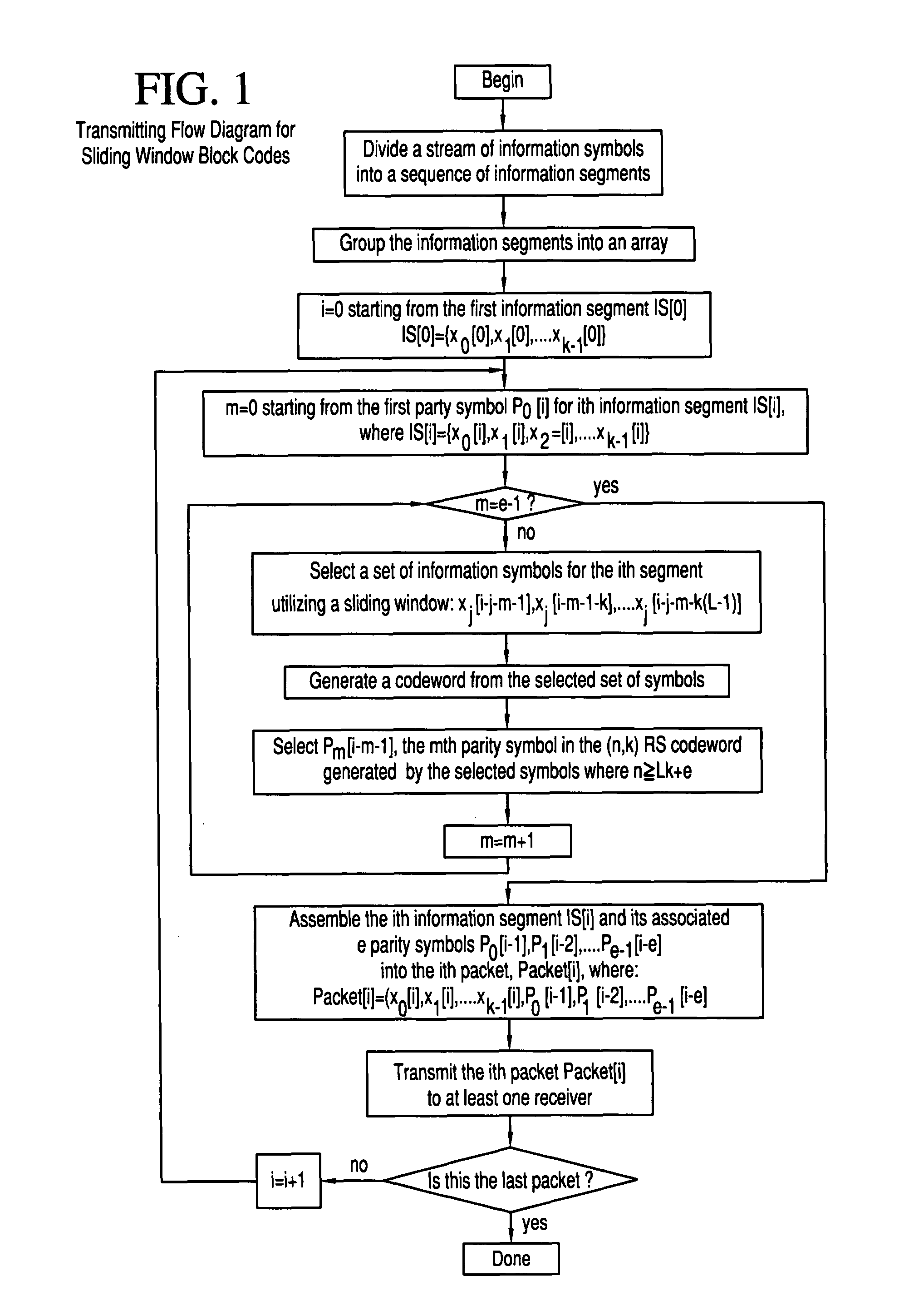
[0043]The transmitter groups the information segments into a 2D array. One of the 2D array indices is the index of the information segment, denoted as i. The other index of the 2D array indices is the index of symbols in the information segment, denoted as j.

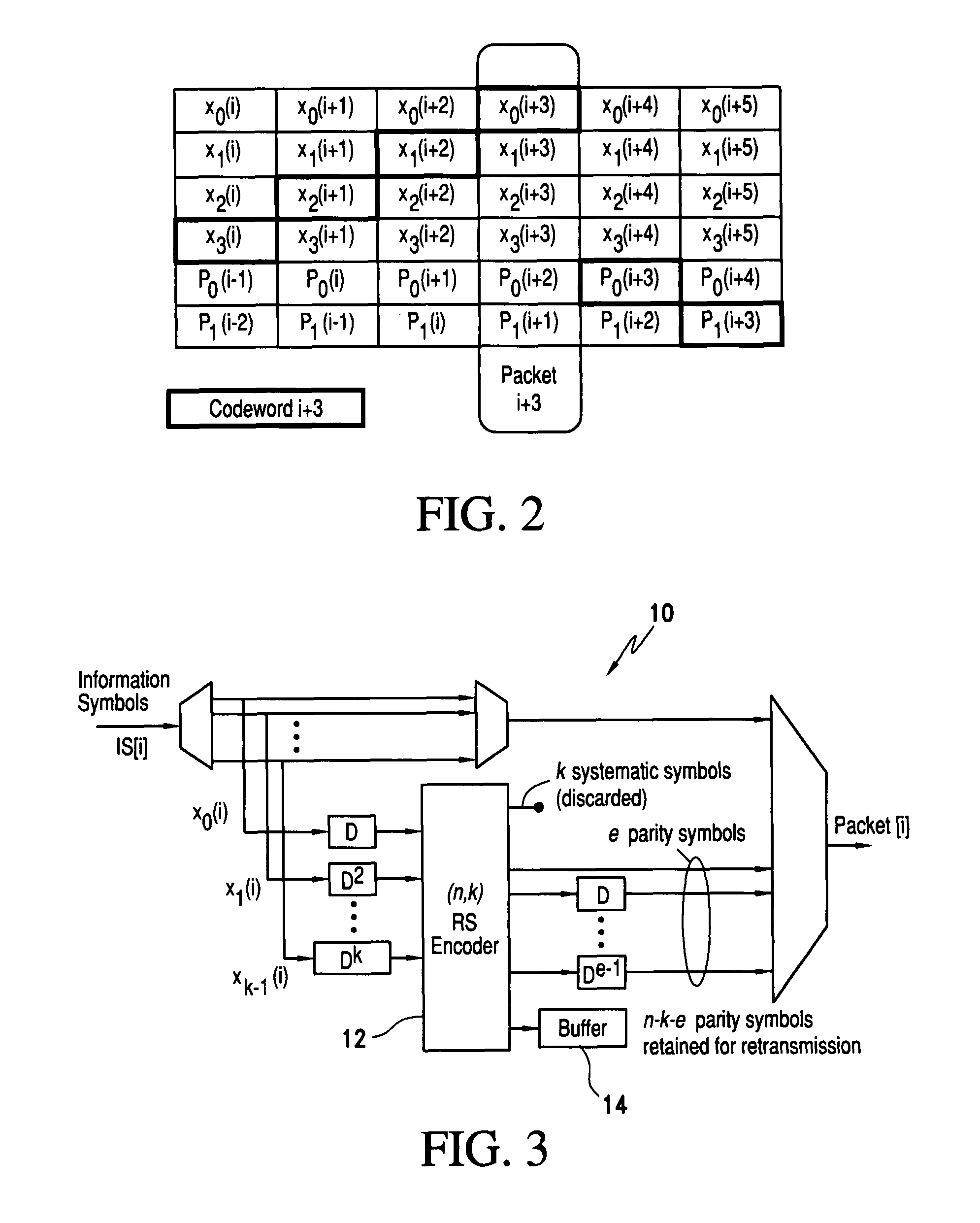
[0044]The transmitter generates a set of e parity symbols associated with each information segment, where e is greater than one. The index of e parity symbols is denoted as m. The mth parity sym...


PUM


Abstract

A block-code-based structure that allows cross-packet coding of data using a sliding window. In this structure, each transmitted packet contains both information symbols and parity symbols generated by the information in previous packets. This code structure allows a receiver to recover lost packets without additional transmissions. If enough packets have been lost so that the receiver cannot recover one or more of them, new parity symbols can be generated and transmitted as additional packets. The parity symbols in these additional packets may be used by multiple receivers. Thus, the sliding window block code reduces retransmission overhead, particularly for multicast applications. Furthermore, the sliding window structure does not produce an encoding delay between the arrival of data and its transmission and reduces the decoding delay between the loss of a packet and its recovery.

Description

BACKGROUND OF THE INVENTION[0001]1. Field of the Invention[0002]The present invention relates generally to network coding techniques and more specifically to network coding techniques that allow receivers to recover lost packets, particularly in multicast applications, while minimizing overhead and latency.[0003]2. Description of the Related Art[0004]Introduction[0005]It is desired to have network coding techniques that allow receivers to recover lost packets while minimizing overhead and latency. In particular, the coding techniques of interest should result in lower latency and overhead than digital fountain (DF) codes. Because information must be encoded across multiple packets, this coding is to be applied to messages that consist of streams of packets. The coding techniques should have the following properties:[0006]1) The code should allow the receiver to recover a certain number of lost packets without requiring retransmissions.[0007]2) The code should minimize ACKs and retra...

Claims


Application Information

Patent Timeline
Patent Type & Authority Patents(United States)
IPC IPC(8): H03M13/00
CPCH03M13/1515H03M13/6306H03M13/3761H03M13/373
Inventor GASS, JOHN H.STEVENS, JAMES A.
Owner ROCKWELL COLLINS INC
Why Eureka
Try Eureka