Method and machine for forming logs of web material, with a mechanical device for forming the initial turn of the logs

a technology of web material and mechanical device, which is applied in the direction of thin material processing, filament handling, article delivery, etc., can solve the problems of frequent cleaning and maintenance operations, particularly complex members, and consequent costs from the point of process control

Active Publication Date: 2011-04-26
FABIO PERINI SPA
View PDF25 Cites 11 Cited by
  • Summary
  • Abstract
  • Description
  • Claims
  • Application Information

AI Technical Summary

Benefits of technology

[0013]An object of the present invention is to provide a method of producing logs of web material around tubular winding cores that overcomes entirely or in part the aforesaid drawbacks.
[0014]The object of a particular embodiment of the present invention is to provide a method that makes it possible to avoid the use of glue, air jets, electrostatic charges, suction or other costly means to form the first turn of web material on winding cores.
[0022]Once the first turn of web material has been formed around the core, the web material is firmly fastened to the winding core and winding of a new log can continue in a reliable manner.
[0027]The mechanical member that causes or facilitates forming of the first turn of web material around the new winding core inserted in the rewinding machine can be controlled by an actuator in synchronism with the movement of the core. For example, there can be provided a sensor which detects the passage of the core in a predetermined positioned and which, as a function of this detection, activates the actuator member which moves said mechanical member. The mechanical member avoids or reduces the need to use glues, suction systems, pressurized air jet systems or electrostatic charges, simplifying the structure of the rewinding machine and eliminating material or power consumption sources.
[0031]According to a different aspect, the invention relates to a rewinding machine for producing logs of web material that simplifies fastening of the web material to each winding core inserted into the machine.
[0034]For example, according to a possible embodiment, the mechanical member can comprise a projection extending in the insertion path of the cores arranged and designed to interact with the cores being fed along said path. Interaction between the projection of the movable mechanical member and the cores causes activation, i.e. movement of the mechanical member and consequently its effect to overturn the initial edge of web material around the core inserted in the insertion path to complete forming of the first turn and thus guarantee fastening of the web material to the core without or with reduced need for electrostatic charges, suction, glue or other measures.

Problems solved by technology

All these known systems require the presence of particularly complex members on the rewinding machine.
When glue is used, it is necessary to provide a glue dispenser, which is a costly member and is susceptible to faults.
Moreover, the glue represents an expendable material that influences the cost of the finished product and can soil the machine, so that frequent cleaning and maintenance operations are required.
In modern gluing devices for winding cores the glue is applied along a longitudinal line on the cylindrical core and this requires precise angular timing of the core during the step for insertion into the rewinding machine, with consequent costs from the viewpoint of process control.
The use of glue on the winding core also has drawbacks from the viewpoint of the finished product, as the last turn or also more than one turn of the material cannot be used as they adhere to the inner core of the roll.
The use of glues also causes problems in the use of removable tubular cores to produce logs without central cores.
This is due to the fact that the glue applied between the tubular core and the first turn of the web material makes it more difficult to remove the core, which then requires to be washed before being subsequently reused in the rewinding machine.
The use of electrostatic charges is not used frequently at present due to the difficulty in charging the winding core and / or the web material sufficiently to obtain suitable adhesion between the initial edge of the web material and the winding core.
Moreover, adhesion by means of electrostatic charges is currently only possible for limited production speeds.

Method used


Image

  • Method and machine for forming logs of web material, with a mechanical device for forming the initial turn of the logs
  • Method and machine for forming logs of web material, with a mechanical device for forming the initial turn of the logs
  • Method and machine for forming logs of web material, with a mechanical device for forming the initial turn of the logs

Examples


Embodiment Construction

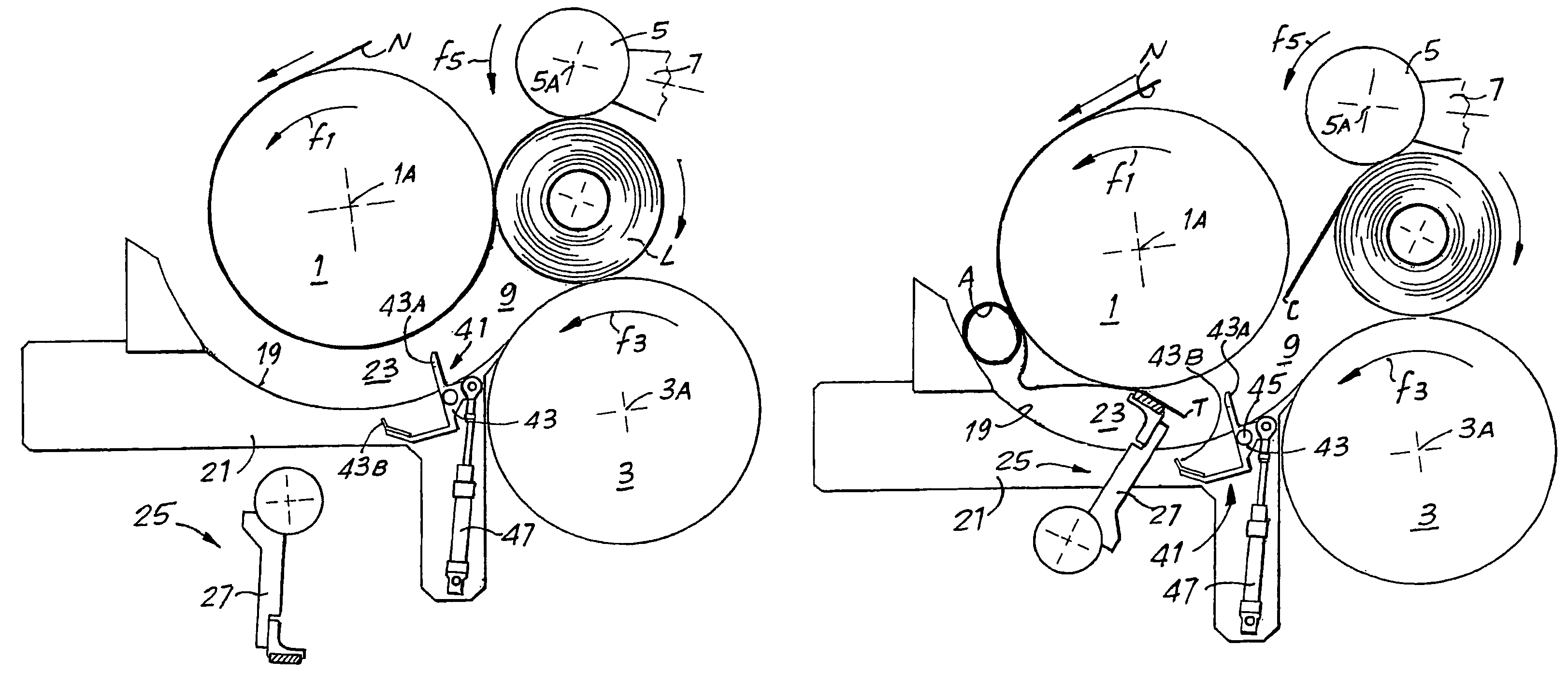
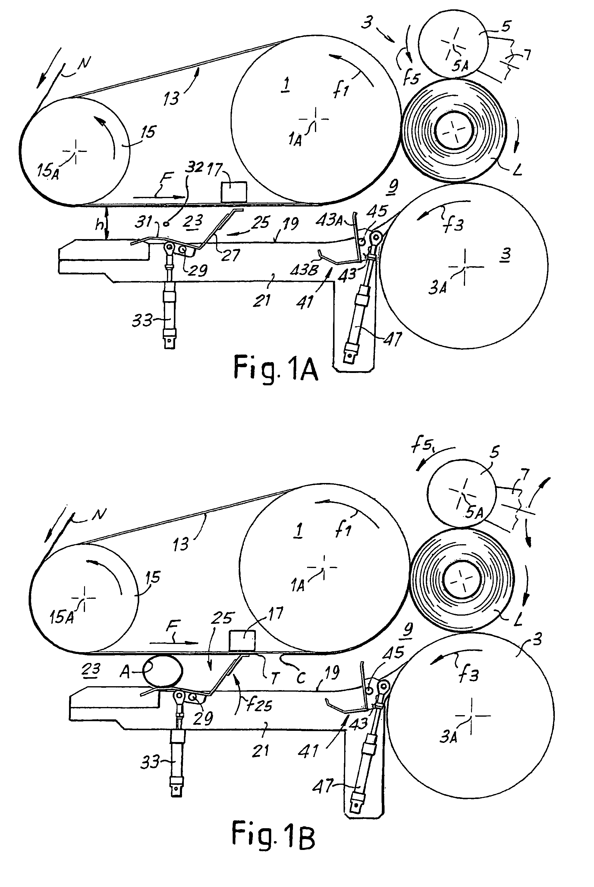
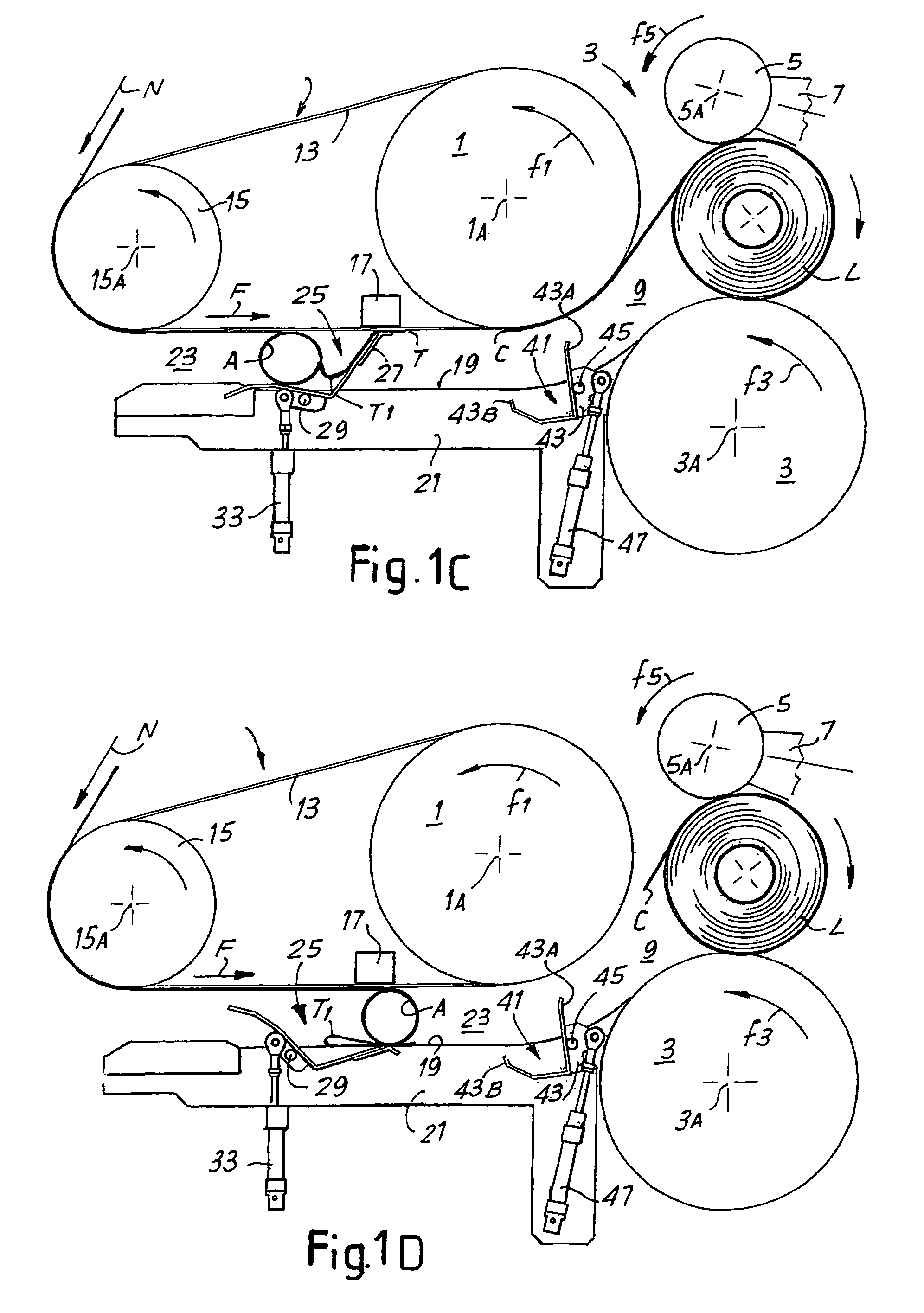
[0053]The accompanying figures show the members of the rewinding machine in different embodiments of the invention, limited to those parts of the machine that are necessary in order to understand the principle on which the invention is based. Other parts of the machine can be designed in a manner known per se to those skilled in the art and, for example, in particular as described in the publications mentioned in the introductory part of this description, the content of which is fully incorporated herein. More specifically, the operating sequence illustrated in the figures of the drawing show the members of the winding head, i.e. those members used to feed the web material and to insert the cores, as well as to sequentially form the individual logs of web material around the respective tubular cores.

[0054]With initial reference to FIGS. 1A to 1F, 3 and 4, the rewinding machine, indicated as a whole with 1, comprises a winding unit 3 including: a first winding roller 1 rotating in th...


PUM


Abstract

The rewinding machine includes a winding unit; a feed path of a web material; a separator device to sever the web material upon completion of winding each log; an insertion path of the winding cores towards the winding unit; a movable mechanical member to facilitate forming a first turn of web material around each winding core inserted in the insertion path.

Description

TECHNICAL FIELD[0001]The present invention relates to methods and machines for producing logs of web material. More specifically, although not exclusively, the present invention relates to methods and machines for producing tissue paper, for example rolls of toilet paper, kitchen towels or the like.STATE OF THE ART[0002]To produce rolls of web material, for example kitchen towels, toilet paper or the like, rewinding machines are used. These machines are fed with a web material, formed by one or more plies of tissue paper or the like, unwound from a reel of large diameter. Predefined quantities of web material are wound on winding cores to form logs, the axial length of which is equal to the width of the web material fed to the rewinding machine and many times greater than the axial length of the small finished rolls intended for use. These logs are subsequently cut into individual rolls of the desired dimension, which are subsequently packaged.[0003]Modern rewinding machines work co...

Claims


Application Information

Patent Timeline
Patent Type & Authority Patents(United States)
IPC IPC(8): B65H19/22
CPCB65H19/2269B65H2408/235B65H19/22B65H19/30
Inventor BENVENUTI, ANGELOMADDALENI, ROMANOCECCHETTINI, LUCAFORNAI, ANDREA
Owner FABIO PERINI SPA
Why Eureka
Try Eureka