
Method for replacing steel wire rope of bridge crane

A bridge crane and wire rope technology, applied in the direction of the clockwork mechanism, load hanging elements, hoisting devices, etc., can solve problems such as restricting production efficiency, adhesion of impurities, affecting the service life of wire ropes, etc.

Inactive Publication Date: 2021-09-14
WUHAN IRON & STEEL GRP ECHENG IRON & STEEL CO LTD
View PDF3 Cites 0 Cited by
  • Summary
  • Abstract
  • Description
  • Claims
  • Application Information

AI Technical Summary

Problems solved by technology

[0003] 1. It is labor-intensive to replace the steel wire rope. Lifting a steel wire rope with a single weight of 1.96kg / m by 20m is equivalent to lifting nearly 60 kg by 20 meters. Moreover, it needs to be lifted 8 times to replace a steel wire rope, which is very labor-intensive.
[0004] 2. The pulley ratio is 4, and there are eight steel wire ropes in total. It is easy to make mistakes in threading and winding when replacing.
[0005] 3. There are unsafe factors
Use hemp rope to bind the steel wire rope. Whether the hemp rope is loose or broken during the lifting process, it is a threat to the personal safety of the staff below.
[0006] 4. Affect the service life of the wire rope
When we install a new wire rope, the wire rope will inevitably be dragged on the ground, so that impurities will stick to the wire rope, which will cause damage to the wire rope during use, thereby shortening the service life of the wire rope
[0007] 5. Long time
It takes 6 hours to replace such a pair of wire ropes, which seriously restricts production efficiency

Method used


Image

  • Method for replacing steel wire rope of bridge crane

Examples


Embodiment Construction

[0020] The technical solutions of the present invention will be clearly and completely described below in conjunction with the accompanying drawings of the present invention. Obviously, the described embodiments are only some of the embodiments of the present invention, not all of them. Based on the embodiments of the present invention, all other embodiments obtained by persons of ordinary skill in the art without making creative efforts belong to the protection scope of the present invention.

[0021] In the description of the present invention, it should be noted that the terms "upper", "lower", "inner", "outer", etc. indicate the orientation or positional relationship is based on the orientation or positional relationship shown in the drawings, or the invention The usual orientation or positional relationship when the product is used is only for the convenience of describing the present invention or simplifying the description, and does not indicate or imply that the referre...


PUM

PropertyMeasurementUnit
Diameteraaaaaaaaaa

Abstract

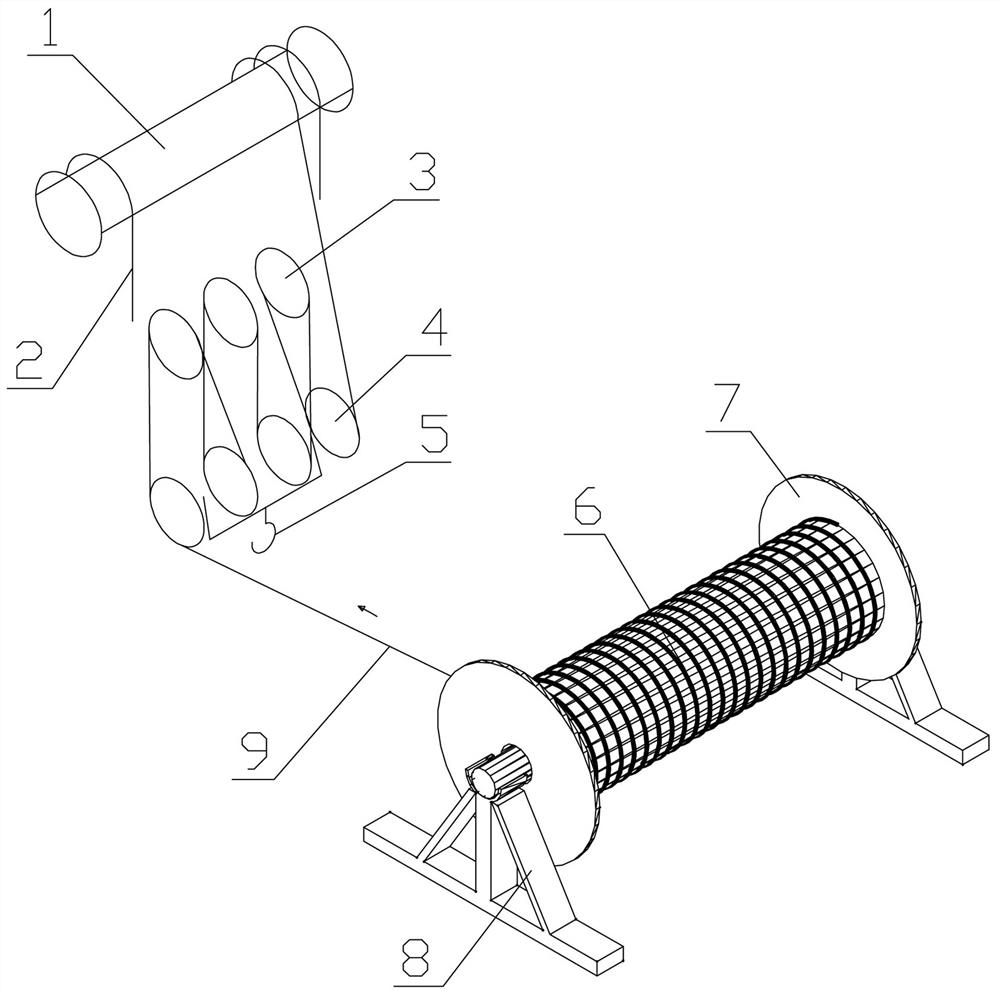
The invention relates to a method for replacing a steel wire rope of a bridge crane, which is characterized by comprising the following steps of: S1, manufacturing a steel frame capable of transversely supporting the whole roll of steel wire rope and rotating, and putting the whole roll of new steel wire rope with the diameter of 22mm on the steel frame; S2, temporarily closing ascending and descending limits in a hoisting mechanism of the bridge crane, and preparing electric welding and a cutting knife in place for cutting and welding a steel wire rope; S3, descending a lifting hook set in the hoisting mechanism to the ground, detaching steel wire rope pressing plates on the two sides of a winding drum, setting the position, two meters away from a movable pulley of the lifting hook set, of the winding drum to cut off, and then connecting the movable pulley with the end of the new steel wire rope in a welded mode; S4, starting the controller to enable the hoisting mechanism to be in an upshift; and S5, starting the hoisting mechanism, integrally winding the new steel wire rope on the winding drum, and lifting the lifting hook set. The method for replacing the steel wire rope is designed for replacing the lifting steel wire rope of the bridge crane hook, is few in working procedures and simple in process.

Description

technical field [0001] The invention relates to the technical field of bridge cranes, in particular to a method for replacing wire ropes of bridge cranes. Background technique [0002] It is very troublesome to replace the steel wire rope of the bridge crane, because the tonnage of the crane is getting larger and larger, and the corresponding wire rope diameter is larger and the length is longer. Take the 45+45 tonnage crane with a relatively small tonnage in many steelmaking plants as an example. Two Ф22mm steel wire ropes are used, single-strand lifting, pulley ratio 4, length 110m, steel wire rope model 6×19, steel core wire rope, steel wire rope fixed on both sides of the drum with a pressure plate, single weight 1.96kg / m, crown block The track elevation is 18m, the lifting height is 20m, and the drum diameter is 600mm. The traditional replacement method is to bind the new rope with hemp rope and lift it manually to bypass between the fixed pulleys and movable pulleys o...

Claims


Application Information

Patent Timeline
IPC IPC(8): B66C13/00B66D1/30B66D1/34B66D1/36B65H75/14B65H75/18
CPCB66C13/00B66D1/30B66D1/34B66D1/36B65H75/14B65H75/18
Inventor 王勇张银洲闵松波李伟李文华冯成张斌刘峰毛勇刚谭守亮
Owner WUHAN IRON & STEEL GRP ECHENG IRON & STEEL CO LTD
Learn More