Voltage regulator with improved transient response

a voltage regulator and transient response technology, applied in the field of voltage regulators, can solve problems such as inferior transient response characteristics, and achieve the effect of improving the transient response characteristics of voltage regulators

Inactive Publication Date: 2011-04-26
ABLIC INC
View PDF11 Cites 7 Cited by
  • Summary
  • Abstract
  • Description
  • Claims
  • Application Information

AI Technical Summary

Benefits of technology

[0017]According to the present invention, because the differential amplifier circuit passes the charge and discharge currents with respect to the gate of the output transistor based on the square of the voltage according to change in drain currents of the transistors in the input stage, a maximum value of the charge and discharge currents becomes larger, transition time of the gate voltage of the output transistor becomes shorter, and transient response characteristics of the voltage regulator become better.

Problems solved by technology

However, in an ordinary voltage regulator, reduced power consumption results in inferior transient response characteristics.

Method used


Image

  • Voltage regulator with improved transient response
  • Voltage regulator with improved transient response
  • Voltage regulator with improved transient response

Examples


Embodiment Construction

[0024]An embodiment of the present invention is described in the following with reference to the attached drawings.

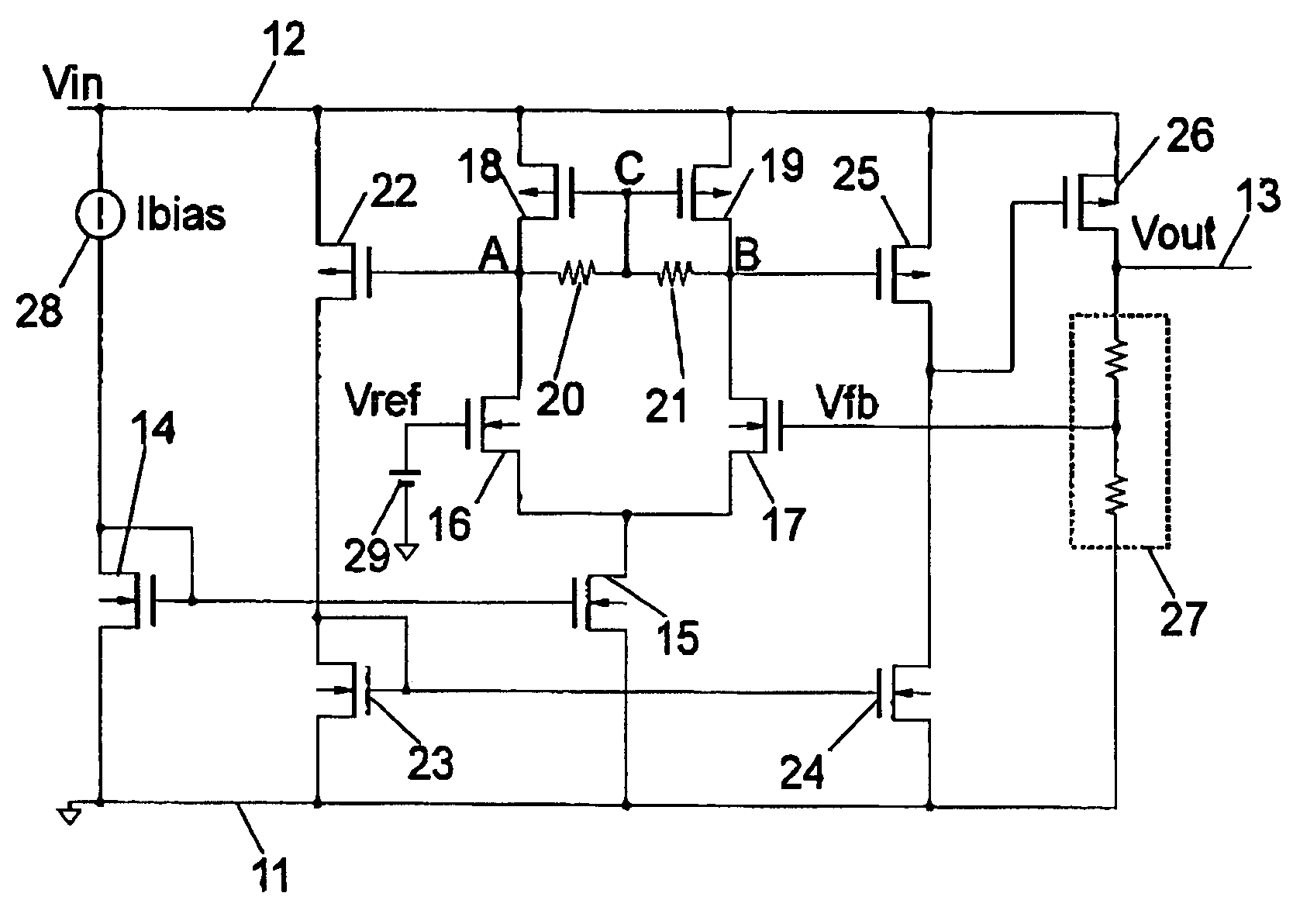
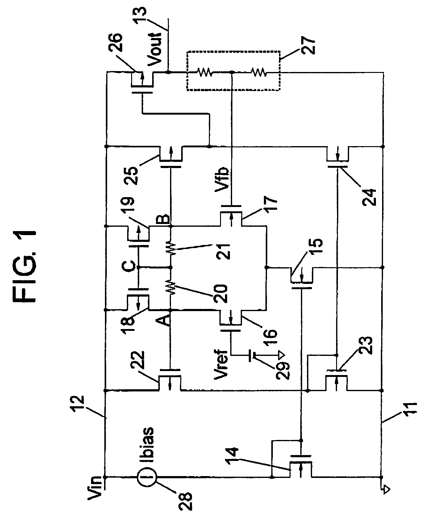
[0025]First, a structure of a voltage regulator is described. FIG. 1 is a circuit diagram illustrating the voltage regulator.

[0026]The voltage regulator has a ground terminal 11, an input terminal 12, an output terminal 13, NMOSs 14 to 17, resistances 20 and 21, NMOSs 23 and 24, PMOSs 18 and 19, a PMOS 22, PMOSs 25 and 26, a voltage divider circuit 27, a constant current circuit 28, and a reference voltage circuit 29.

[0027]The constant current circuit 28 is provided between the input terminal 12 and a drain of the NMOS 14. A source of the NMOS 14 is connected to the ground terminal 11 while a gate of the NMOS 14 is connected to the drain of the NMOS 14 and a gate of the NMOS 15. A source of the NMOS 15 is connected to the ground terminal 11 while a drain of the NMOS 15 is connected to sources of the NMOSs 16 and 17. The reference voltage circuit 29 is provided between t...


PUM


Abstract

Provided is a voltage regulator having satisfactory transient response characteristics. Because a PMOS (25) and an NMOS (24) pass drain currents (charge and discharge currents with respect to gate of PMOS (26)) based on the square of voltage (ΔIR) according to change (ΔI) in drain currents of NMOSs (16 and 17), a maximum value (Imax) of the charge and discharge currents becomes larger, transition time (t) of gate voltage of the PMOS (26) becomes shorter, and the transient response characteristics of the voltage regulator become better.

Description

BACKGROUND OF THE INVENTION[0001]1. Field of the Invention[0002]The present invention relates to a voltage regulator.[0003]2. Description of the Related Art[0004]A conventional voltage regulator is described. FIG. 4 is a circuit diagram illustrating a conventional voltage regulator.[0005]NMOSs 46 and 47, PMOSs 48 and 49, NMOSs 53 and 54, a PMOS 52, and a PMOS 55 form a differential amplifier circuit. In the differential amplifier circuit, gates of the NMOSs 46 and 47 are input terminals while drains of the PMOS 55 and the NMOS 54 are output terminals. The PMOS 55 and NMOS 54 form a push-pull circuit. NMOSs 44 and 45 form a current mirror circuit and have constant current characteristics. A constant current circuit 58 and the NMOSs 44 and 45 function as a current supply means to the differential amplifier circuit.[0006]Input voltage Vin which is power supply voltage is input to an input terminal 42. A PMOS 56 outputs to an output terminal 43 output voltage Vout which is controlled to...

Claims


Application Information

Patent Timeline
Patent Type & Authority Patents(United States)
IPC IPC(8): G05F1/575
CPCG05F1/565G11C5/14G11C7/10
Inventor IMURA, TAKASHI
Owner ABLIC INC
Why Eureka
Try Eureka