Coaxial cable connector system and method

a technology of coaxial cable and connector, which is applied in the direction of coupling device connection, coupling device details, electric discharge lamps, etc., can solve the problem of not providing adequate shielding for rf applications

Active Publication Date: 2011-05-03
UBIQUITI INC
View PDF23 Cites 19 Cited by
  • Summary
  • Abstract
  • Description
  • Claims
  • Application Information

AI Technical Summary

Benefits of technology

[0005]Disclosed herein is a system and method for a connecting device comprising a body having a threaded portion and a sleeve portion. A plurality of coaxial receptacles disposed in the threaded portion, each receptacle formed to couple with element of a coaxial cable connector, and a plurality of coaxial mounts disposed on the sleeve end. The coaxial mounts may be coupled to coaxial leads with each lead having a mini-connectors. The body is substantially similar to a type-n connector and provides for easy coupling of multiple coaxial cables within a single connector housing.

Problems solved by technology

While, these connectors may be well suited for many applications, they do not provide for adequate shielding for RF applications.

Method used


Image

  • Coaxial cable connector system and method
  • Coaxial cable connector system and method
  • Coaxial cable connector system and method

Examples


Embodiment Construction

[0026]Specific examples of components and arrangements are described below to simplify the present disclosure. These are, of course, merely examples and are not intended to be limiting. In addition, the present disclosure may repeat reference numerals and / or letters in the various examples. This repetition is for the purpose of simplicity and clarity and does not in itself dictate a relationship between the various embodiments and / or configurations discussed.

[0027]Read this application with the following terms and phrases in their most general form. These definitions are provided to facilitate a clear understanding of the present invention. The general meaning of each of these terms or phrases is illustrative, and not in any way limiting.

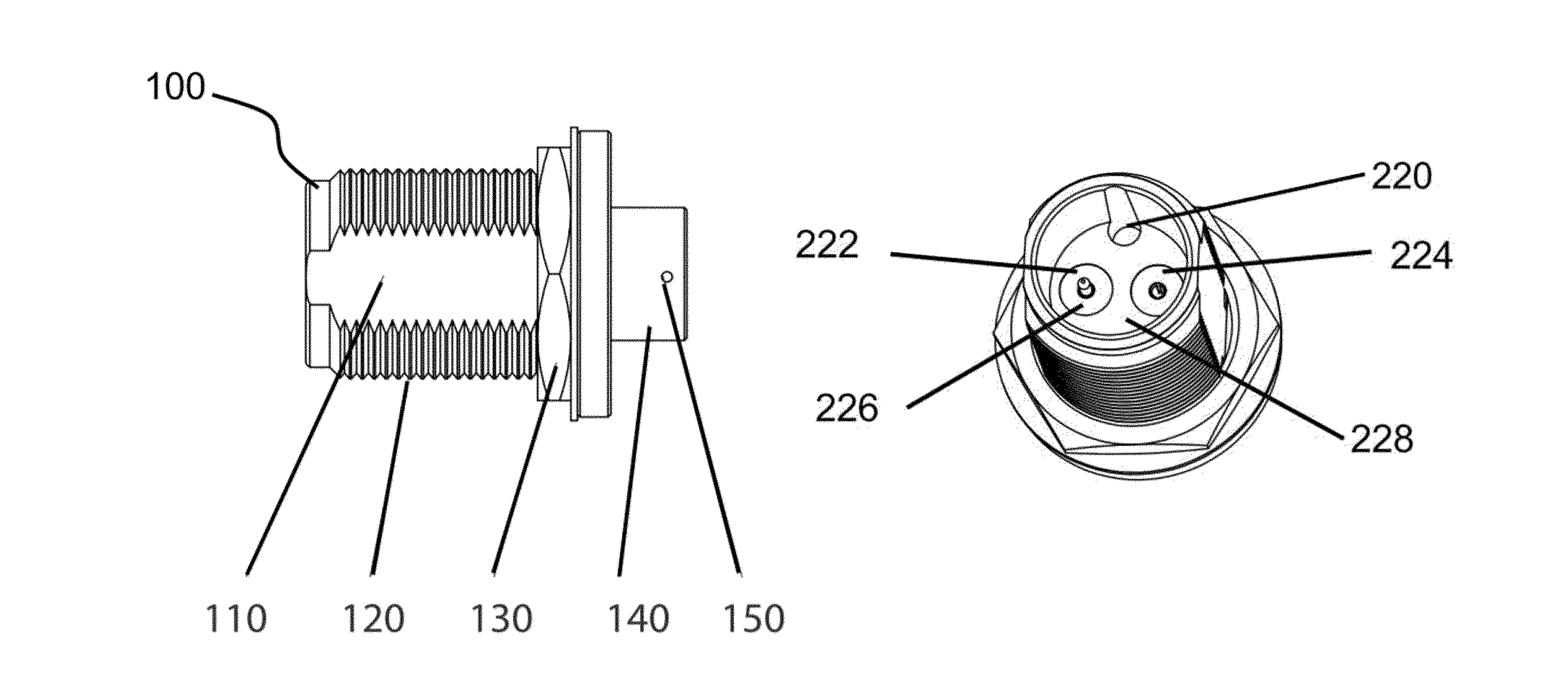
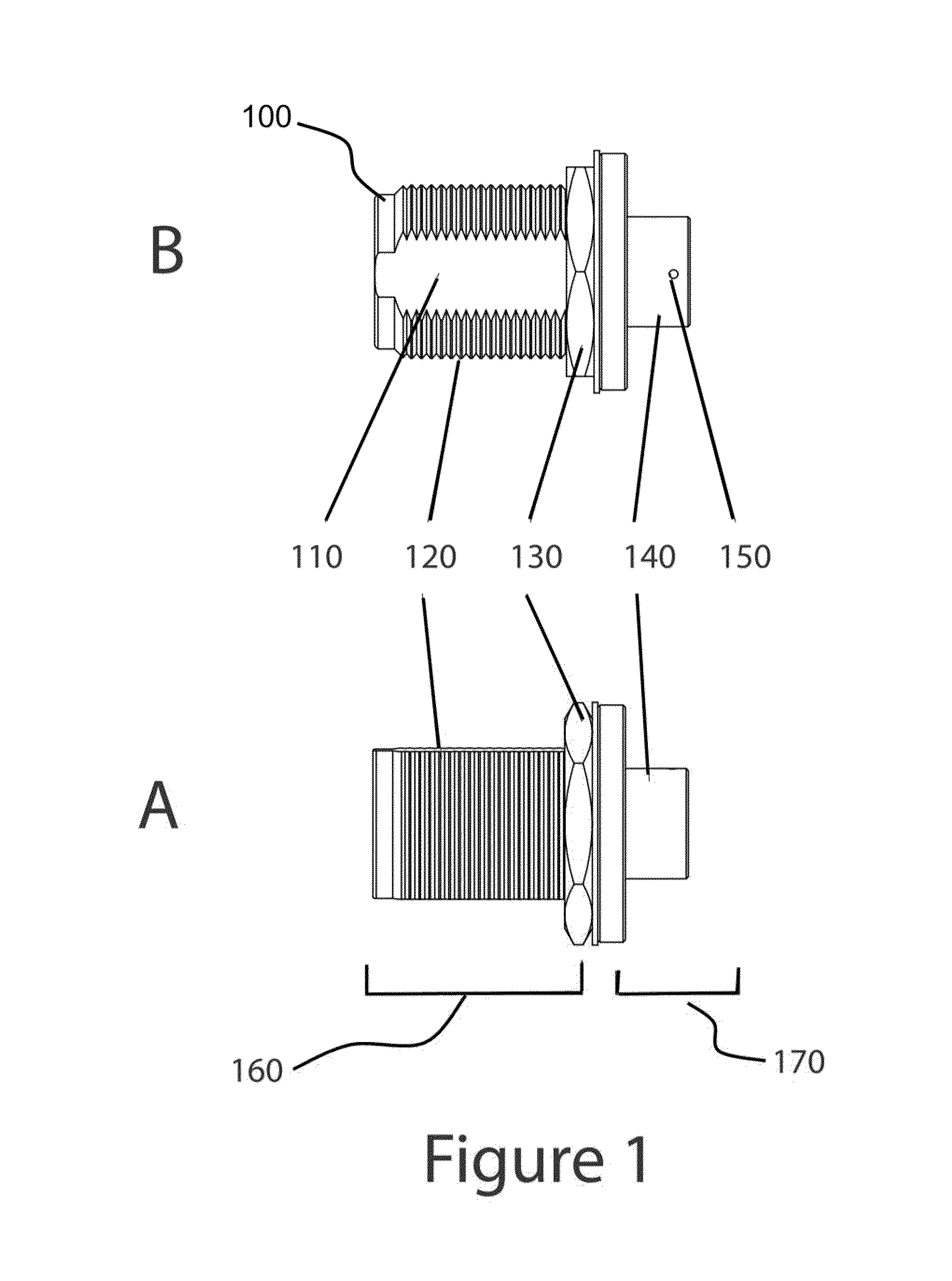
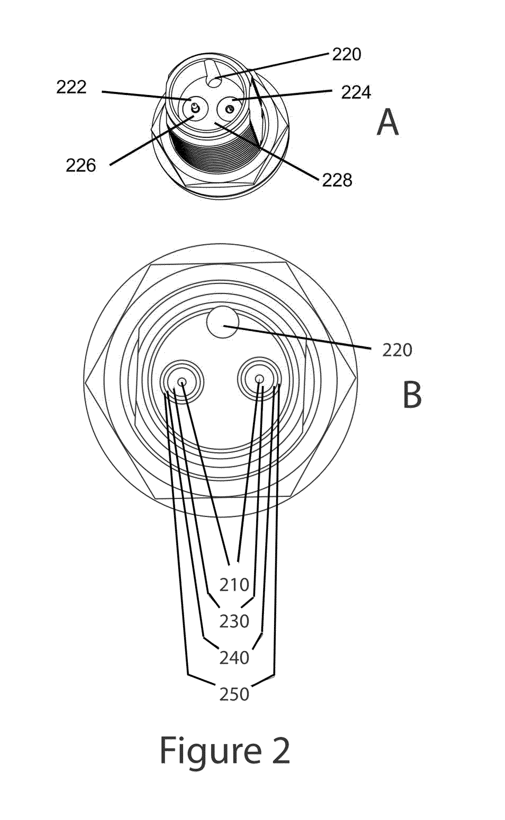
[0028]FIG. 1 illustrates a side view and a top view respectively of one aspect of a coaxial cable connector system. In the FIG. 1A, a body 100 having a threaded side 160 is disposed for mating with multiple coaxial cables. The body 100 is preferably...


PUM


Abstract

A connecting device comprising a body having a threaded portion and a sleeve portion. A plurality of coaxial receptacles disposed in the threaded portion, each receptacle formed to couple with element of a coaxial cable connector, and a plurality of coaxial mounts disposed on the sleeve end. The coaxial mounts may be coupled to coaxial leads with each lead having a mini-connectors. The body is substantially similar to a type-n connector and provides for easy coupling of multiple coaxial cables within a single connector housing.

Description

FIELD OF THE INVENTION[0001]The disclosure herein relates generally to device for connecting coaxial cables, specifically for connecting a plurality of coaxial cables using a single connector housing.BACKGROUND[0002]Coaxial cables are an ideal medium for transmitting radio frequency (“RF”) and microwave signals. Such cables are defined as an electrical cable with an inner, center conductor surrounded by 3 tubular, coaxial layers being, from innermost to outer most, a dielectric layer, a conductive layer and an insulating layer. Generally, the center conductor is operable for the transmission of the RF signal, and the conductive layer (also known as the “shield”) provides the return electrical path to the RF power stage. The cables provide both good signal isolation and low signal loss. Due to the wide spread acceptance and use of coaxial cables, many types of connectors are in use. A number of improvements have been made recently to coaxial connectors, predominantly though, for conv...

Claims


Application Information

Patent Timeline
Patent Type & Authority Patents(United States)
IPC IPC(8): H01R9/05
CPCH01R27/00H01R24/52H01R13/746H01R2107/00
Inventor PERA, ROBERT J.
Owner UBIQUITI INC
Why Eureka
Try Eureka