Ostomy mounting wafer and a method of preparing it

a technology of mounting wafers and ostomy, which is applied in the field of ostomy wafers, can solve the problems presenting environmental problems and achieves the effect of other materials, and increasing the use of adhesives

Inactive Publication Date: 2011-05-03
COLOPLAST AS
View PDF13 Cites 3 Cited by
  • Summary
  • Abstract
  • Description
  • Claims
  • Application Information

AI Technical Summary

Benefits of technology

[0028]An interesting embodiment is one comprising, during the step of providing the radiation, maintaining, using a fastening means, the first and second parts in the abutting position, the step of providing the radiation comprising providing the radiation through the fastening means. This fastening means may have a fourth absorption coefficient at the predetermined wavelength, which fourth absorption coefficient ensures that the intensity loss of the radiation when travelling through the fastening means is sufficiently low to leave sufficient radiation for the welding / melting and to not damage the fastening means.
[0029]In that embodiment, the radiation may be provided through the fastening means while maintaining the first and second parts in the desired position. In this manner, full freedom is obtained to select how to hold the first and second parts during the welding / radiation. If positions for the fastening means are selected where the radiation is provided to the zone(s), the fastening means may be selected with a suitable (low) absorption coefficient to allow transmission of the radiation there through without excessive loss of radiation intensity and excessive heating of the fastening means.

Problems solved by technology

However, for a number of reasons, the use of adhesives has been rejected as the proper way of attaching these parts.
One such reason is the fact that the adhesive may present an environmental problem.
Also, the use of adhesives adds a number of demands as to the adhesive and other materials useable.
In addition, the long term stability of the adhesive connection is questionable.
Heat sealing / welding, on the other hand, avoids the use of adhesives but it results in the parts being deformed at the sealing due to the heat and pressure applied.
Thus, both the dimensions required by the welding and the undesired dimension changes caused by the welding will provide weak zones and generally prevent the element from being useful for connection purposes in the area around the welding zone.

Method used


Image

  • Ostomy mounting wafer and a method of preparing it
  • Ostomy mounting wafer and a method of preparing it
  • Ostomy mounting wafer and a method of preparing it

Examples


Embodiment Construction

[0070]Further scope of applicability of the present invention will become apparent from the detailed description given hereinafter. However, it should be understood that the detailed description and specific examples, while indicating preferred embodiments of the invention, are given by way of illustration only, since various changes and modifications within the spirit and scope of the invention will become apparent to those skilled in the art from this detailed description.

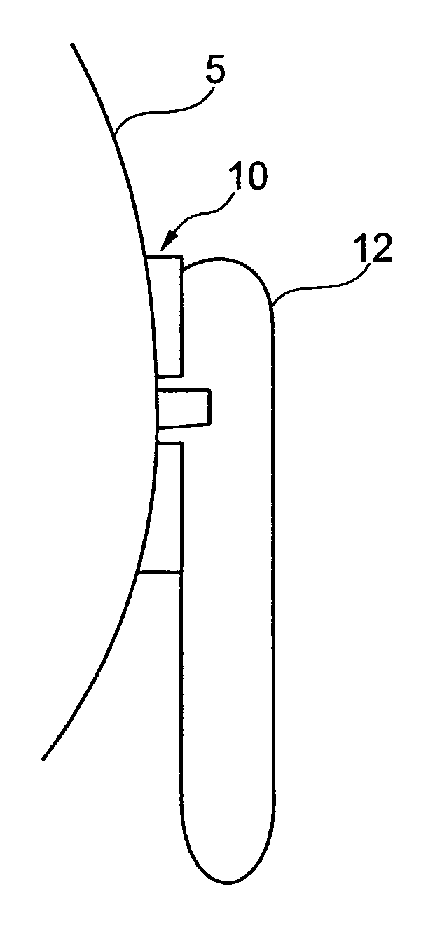
[0071]FIG. 1 illustrates an ostomy bag 12 attached to a body side mounting wafer 10 attached to a person 5 and around a stoma. The wafer serves the purpose of, consecutively, attaching a number of bags to the person without having to detach the wafer from the skin of the person.

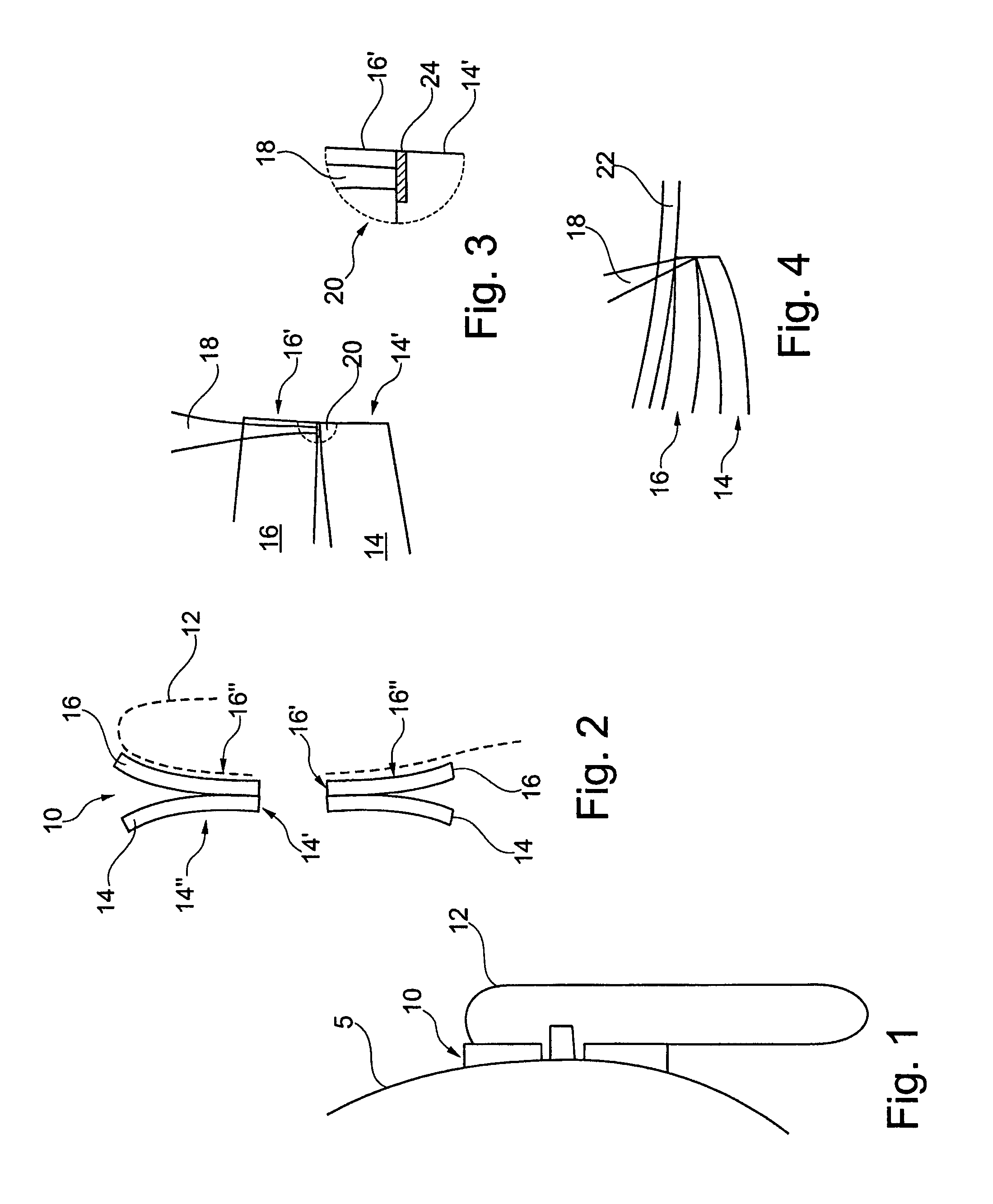
[0072]The wafer (see FIG. 2) actually is formed of two parts 14 and 16 which each has an opening for the stoma; the openings have edges 14′ and 16′. In the present embodiment, the edges 14′ and 16′ are coextending.

[0073]Naturally, one of t...


PUM

PropertyMeasurementUnit
distanceaaaaaaaaaa
smoothnessaaaaaaaaaa
lengthaaaaaaaaaa

Abstract

An ostomy body side mounting wafer and a method of preparing the ostomy body side mounting wafer, where the wafer is assembled from two parts using laser welding. The laser light is provided through one of the parts having a low or lower absorption of the laser light. The other part has a higher absorption of the laser light, whereby the interface between the two parts is heated at the welding zone(s) of the laser light. In this manner, an assembly is obtained independently of the thicknesses of the materials and even close to openings or other edges.

Description

[0001]This is a nationalization of PCT / DK2004 / 000728 filed 21 Oct. 2004 and published in English.BACKGROUND OF THE INVENTION[0002]1. Field of the Invention[0003]The present invention relates to an ostomy wafer which is the part of an ostomy bag set mounted to the person and to which detachable ostomy bags may be mounted.[0004]2. Description of the Related Art[0005]Normally, in order to obtain suitable flexibility, ostomy mounting wafers are prepared by fixing two parts to each other, where one part is adapted to be fixed to the person and the other part is adapted to form a landing zone for the ostomy bag. These parts are attached at the ostomy opening. However, this attachment must both be strong and sealed in order to prevent leaking.[0006]Hitherto, this assembly / sealing has been performed by either using adhesives or heat welding.[0007]Using adhesives provides a wider range of possibilities as to the actual shape of the attachment area and the thickness of the materials at the zo...

Claims


Application Information

Patent Timeline
Patent Type & Authority Patents(United States)
IPC IPC(8): A61F5/44A61F5/448B23K26/00B29C35/08B29C65/00B29C65/14B29C65/16
CPCA61F5/448B29C65/1435B29C65/148B29C65/1483B29C65/1635B29C65/168B29C65/1683B29C66/81267B29C66/112B29C66/1122B29C66/131B29C66/472B29C66/474B29C66/54B23K26/206B29C66/5346B29C65/1412B29C65/1416B29C65/1616B29L2031/7148B29L2031/737B29L2031/753B29C65/1612B29C65/1419B29C65/1619B29C66/5344
Inventor BAGER, KIMFINK, INGRID LAESOE
Owner COLOPLAST AS
Why Eureka
Try Eureka