Head mounted display

a display and head technology, applied in the field of head mounted displays, can solve the problems of increasing frame weight, reducing design properties or raising costs, increasing the weight of frames, and increasing the fatigue of observers, so as to enhance the rigidity of front portions of frames, increase the weight of frames, and prevent the effect of observation fatigu

Inactive Publication Date: 2011-05-03
SONY CORP
View PDF8 Cites 107 Cited by
  • Summary
  • Abstract
  • Description
  • Claims
  • Application Information

AI Technical Summary

Benefits of technology

[0011]In order to solve this problem, it may be contemplated to enhance the rigidity of the front portion 1011 of the frame 1010. Such solving means, however, probably needs an increase in the cross-sectional area of the frame or the use of a material having a high modulus of longitudinal elasticity, which normally leads to an increased frame weight, lowered design properties or a raised cost.
[0023]In the head mounted display (HMD) according to the embodiment of the present invention, the connecting member connects the two image display devices to each other, and the connecting member is mounted to that central portion of the frame which is located between the two pupils of the observer. In other words, the image display devices are not mounted directly to the frame. Therefore, even in the case where upon mounting of the frame onto the observer's head, the temple portions are spread toward the outer sides with the result of a deformation of the frame, such a deformation of the frame leads to no or extremely little, if any, displacement (positional change) of the image generating devices or the light guide means. Accordingly, generation of a change in the angle of convergence between left and right images can be securely prevented from occurring. Moreover, since it is unnecessary to enhance the rigidity of a front portion of the frame, it is possible to obviate the generation of an increase in the weight of the frame, a lowering in design properties, or an increase in cost. Besides, since the image display devices are not mounted directly to the frame resembling a frame of an ordinary pair of eyeglasses, the design and color and the like of the frame can be freely selected according to the observer's taste, and there are few restrictions imposed on the design of the frame; thus, there is a high degree of freedom on a design basis. In addition, the connecting member is located between the observer and the frame, and the projected image of the connecting member is included in the projected image of the frame. In other words, when the head mounted display is viewed from the front side of the observer, the connecting member is hidden behind the frame. Therefore, high design properties can be imparted to the head mounted display.

Problems solved by technology

As a result, a mismatch is generated in a preadjusted spatial distance from the observer to the virtual image, whereby the observer grows fatigued at the time of observation.
Such solving means, however, probably needs an increase in the cross-sectional area of the frame or the use of a material having a high modulus of longitudinal elasticity, which normally leads to an increased frame weight, lowered design properties or a raised cost.
In addition, since the image display devices 100 are mounted to the frame 1010 resembling a frame of a pair of eyeglasses, it is difficult to freely select the design, color or the like of the frame 1010 according to the observer's taste.
Besides, due to many restrictions imposed on the design of the frame 1010, the degree of freedom on a design basis is not high.

Method used


Image

  • Head mounted display
  • Head mounted display
  • Head mounted display

Examples


example 1

2. EXAMPLE 1

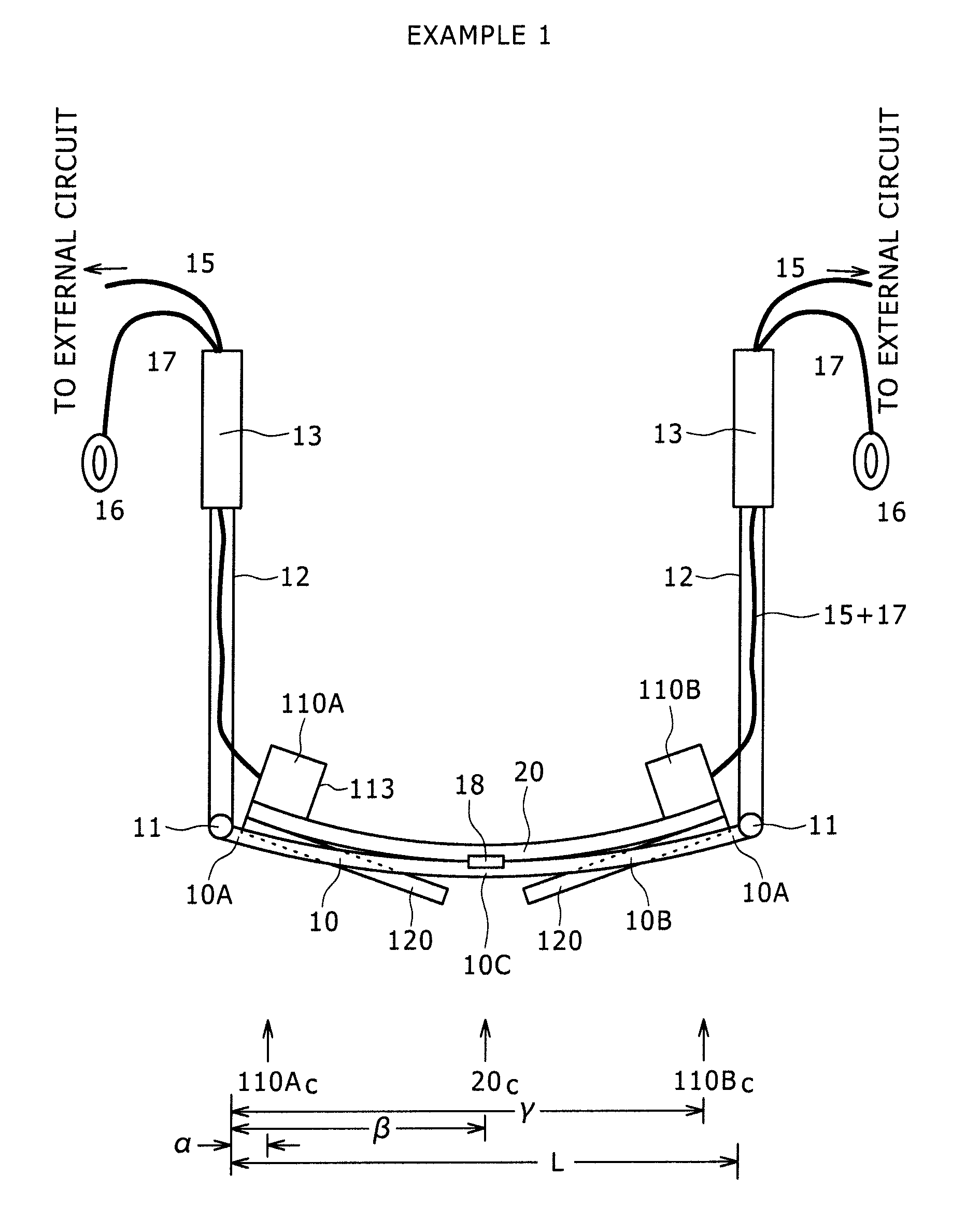
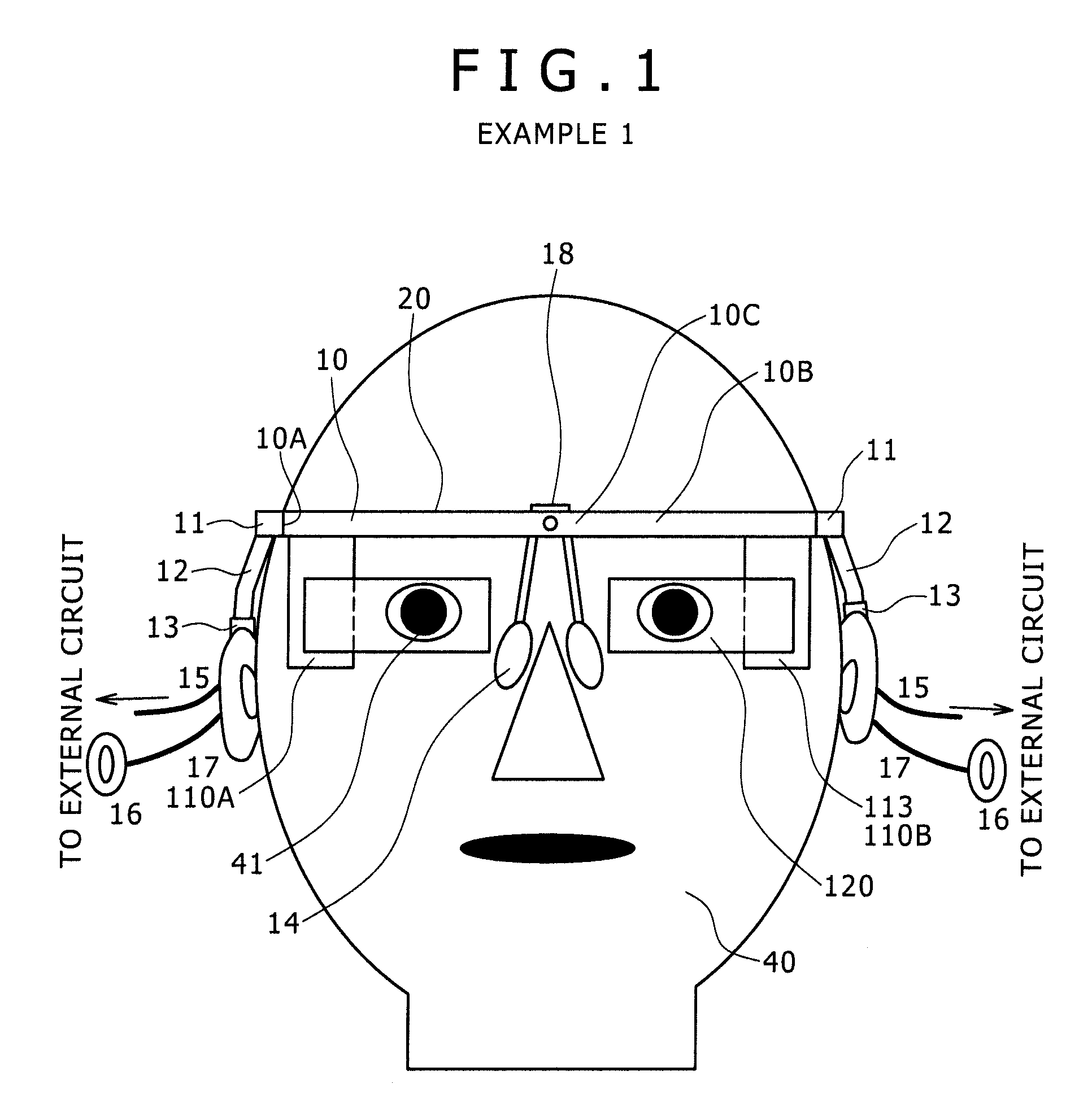
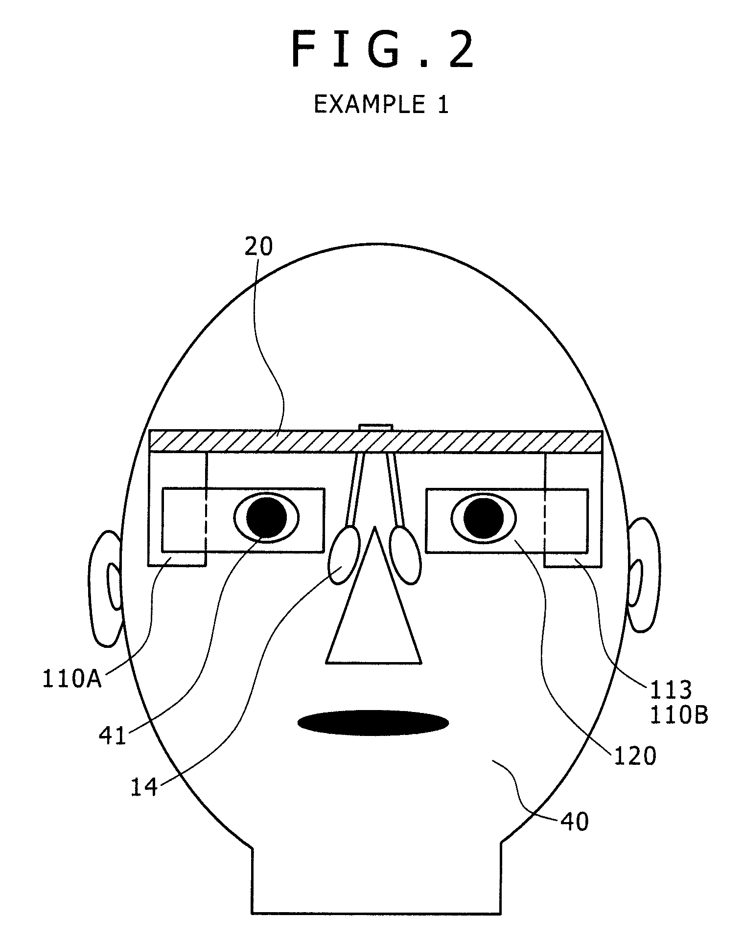
[0130]Example 1 relates to a head mounted display according to an embodiment of the present invention. FIG. 1 shows a schematic view of the head mounted display of Example 1, as viewed from the front side, and FIG. 2 shows a schematic view of the head mounted display of Example 1 (in an assumed condition where a frame is removed), as viewed from the front side. In addition, FIG. 3 shows a schematic view of the head mounted display of Example 1, as viewed from the upper side, and FIG. 4 shows the condition where the head mounted display of Example 1 is mounted to the head of an observer 40, as viewed from the upper side. Incidentally, in FIG. 4, only the image display devices are shown and the frame is omitted, for convenience. Besides, FIG. 5 shows a perspective view of the head mounted display of Example 1, as viewed from a front upper side, and FIG. 6 shows a perspective view of the same as viewed from a rear lower side. Further, FIG. 7 shows an exploded view of compon...

example 2

3. EXAMPLE 2

[0157]Example 2 resides in a modification of Example 1. FIG. 9 shows a conceptual diagram of an image display device 200 in a head mounted display according to Example 2. As shown in FIG. 9, in Example 2, an image generating device 210 includes an image generating device of the second configuration. Specifically, the image generating device includes:

[0158](a) a light source 251;

[0159](b) a collimating optical system 252 by which beams emitted from the light source 251 are made to be parallel beams;

[0160](c) a scanning section 253 configured to scan the parallel beams emitted from the collimating optical system 252; and

[0161](d) a relay optical system 254 by which the parallel beams scanned by the scanning section 253 are relayed and emitted. Incidentally, the image generating device 210 as a whole is accommodated in a casing 213 (in FIG. 9, indicated by dot-dash lines). The casing 213 is provided with an aperture (not shown), and the beams are emitted from the relay opti...

example 3

4. EXAMPLE 3

[0164]Example 3 also resides in a modification of Example 1. FIG. 10A shows a conceptual diagram of an image display device 300 in a head mounted display according to Example 3. Besides, FIG. 10B shows a schematic sectional view illustrating part of a reflection-type volume holographic diffraction grating, in an enlarged form. In Example 3, an image generating device 110 includes an image generating device of the first configuration, in the same manner as in Example 1. In addition, an optical device 320 is the same as the optical device 120 of Example 1 in basic configuration or structure, as it includes:

[0165](a) a light guide plate 321 which as a whole is disposed on the side of the center of the face of the observer 40 relative to the image generating device 110, on which the beams emitted from the image generating device 110 are incident, through which the beams are guided, and from which the beams are emitted toward the pupil 41 of the observer 40;

[0166](b) a first ...


PUM


Abstract

Disclosed herein is a head mounted display including: an eyeglasses frame-like frame to be mounted onto an observer's head; and two image display devices, each of the image display devices including an image generating device, and light guide means which is mounted to the image generating device, which as a whole is located on the side of the center of an observer's face relative to the image generating device, on which beams emitted from the image generating device are incident, through which the beams are guided, and from which the beams are emitted toward an observer's pupil.

Description

[0001]The present application contains subject matter related to that disclosed in Japanese Priority Patent Application JP 2008-324642 filed in the Japan Patent Office on Dec. 19, 2008, the entire content of which is hereby incorporated by reference.BACKGROUND OF THE INVENTION[0002]1. Field of the Invention[0003]The present invention relates to a head mounted display including an eyeglasses frame-like frame to be mounted onto an observer's head and image display devices.[0004]2. Description of the Related Art[0005]A virtual image display device (image display device) for permitting a two-dimensional image formed by an image forming device to be observed by an observer (viewer) as a magnified virtual image through a virtual image optical system has been known, for example from Japanese Patent Laid-open No. 2006-162767 (hereinafter referred to as Patent Document 1).[0006]As illustrated by a conceptual diagram shown in FIG. 8, this image display device 100 includes an image forming dev...

Claims


Application Information

Patent Timeline
Patent Type & Authority Patents(United States)
IPC IPC(8): G02B27/14
CPCG03B21/26G02B27/0176G02B27/0172G02B6/00
Inventor MUKAWA, HIROSHIFUNANAMI, AKIOGOTO, TEIYU
Owner SONY CORP
Why Eureka
Try Eureka