
Image forming apparatus and image forming method

a technology of image forming apparatus and forming method, which is applied in the direction of electrographic process apparatus, instruments, optics, etc., can solve the problems of unfavorable image density, unfavorable image scattering, and difficulty in stably maintaining a charge amount of toner, so as to achieve stable image quality and suppress the effect of toner scatter

Inactive Publication Date: 2011-05-03
KYOCERA DOCUMENT SOLUTIONS INC
View PDF16 Cites 12 Cited by
  • Summary
  • Abstract
  • Description
  • Claims
  • Application Information

AI Technical Summary

Benefits of technology

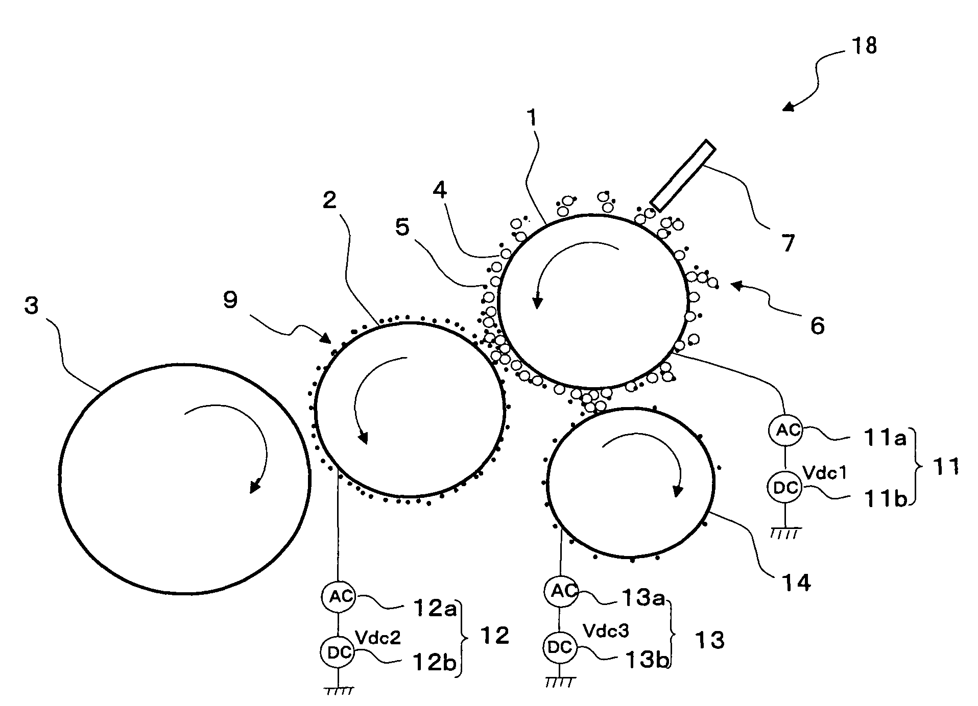
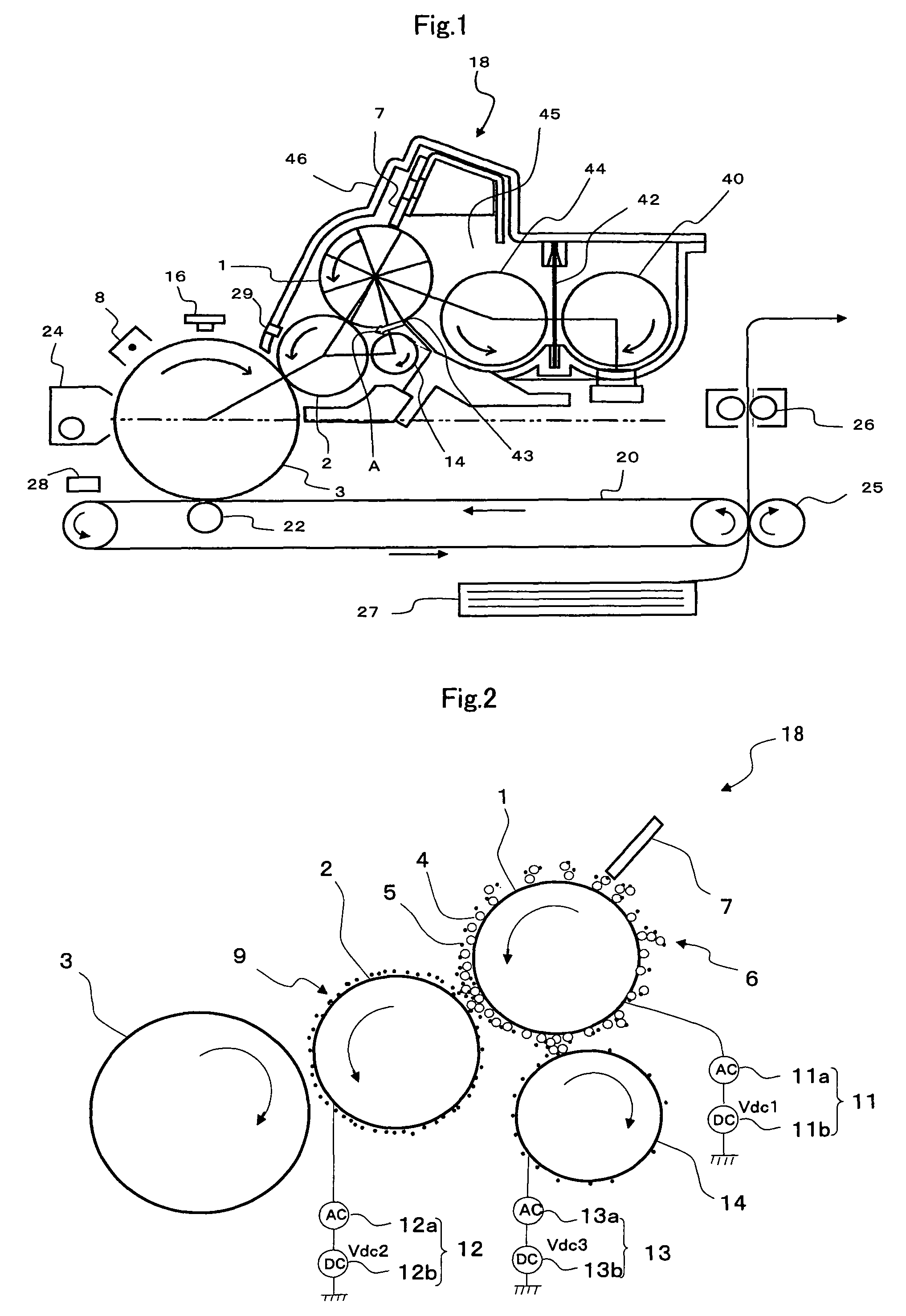
The present invention provides an image forming apparatus and method that can suppress toner scatter and maintain stable development characteristics over a long period of time. This is achieved by providing a toner collecting roller that collects scattered toner and applies a bias voltage to it, and by controlling the bias voltage based on the toner charge amount and surface potential of the toner holding body. The apparatus and method can provide a stable image for a long time and improve image quality.

Problems solved by technology

However, in the one-component developing method, it is difficult to stably maintain a charge amount of the toner.
However, in this developing method, the two-component developing method and the one-component developing method are combined, thereby posing a problem in that there is a difference between an appropriate charge amount of the toner when the electrostatic latent image is developed and an appropriate charge amount of the toner when the toner thin layer is formed.
Thus, in some cases, a small amount of the toner in the toner thin layer causes an unfavorable image density, or a problem of development ghost and the like because of poor peeling of the toner thin layer that did not contribute to the development is posed.
However, as described above, since the optimal toner charge amount differs between at the time of thin layer formation and at the time of development, the above-described means may be insufficient as the measures.
Meanwhile, one of causes that pose the above-described problems is influence of scattered toner.
The scattered toner occurring in the developing apparatus scatters to the inside of an electrophotographic apparatus in which the electrostatic latent image holding body, an optical system apparatus, a charging apparatus, a transfer apparatus and the like are arranged, thereby resulting in various poor images, improper operations and the like including the above-described problems.
Particularly in the touchdown developing method, the scattered toner may affect the toner thin layer on the developing roller, thereby causing image disturbance, and thus, the toner scatter needs to be further suppressed.
Moreover, in the touchdown developing method, since the toner density of the two-component developer is high, and the fluidity of the developer is unsatisfactory, when the magnetic brush is collected in a two-component developer containing part, the developer is sequentially collected and pressed and compressed, so that air has nowhere to go and the toner is discharged outside together with the air, which easily causes the toner scatter.
In Patent Document 3, when the toner is peeled from the collecting roller, which collected the scattered toner, to return the same to the developing apparatus, a channel to return the toner through needs to be separately provided, which disadvantageously makes the apparatus larger.
Particularly, in a high-speed machine employing the touchdown developing method and having a drum linear velocity of 180 mm / sec or more, the system in which in order to suppress deterioration of the developer, the total amount of the developer is increased may easily cause the toner scatter.
However, since this varies the potential difference ΔV in a direction in which it is hard for the toner to move from the magnetic brush formed on the magnetic roller to the toner holding body, the two-component developer is collected into the two-component developer containing part while leaving much toner that does not contribute to the toner thin layer formation in the magnetic brush on the magnetic roller, thereby resulting in a state where the toner scatter more easily occurs.
That is, since the difference in toner charge amount makes the potential difference ΔV differ, and in turn this difference in potential difference ΔV makes the scatter toner amount differ, there is a problem in that in the case where collecting power of the collecting roller is set to be constant, the toner scatter cannot be suppressed.

Method used


Image

  • Image forming apparatus and image forming method
  • Image forming apparatus and image forming method
  • Image forming apparatus and image forming method

Examples


first embodiment

Modification of First Embodiment

[0103]The control of the bias voltage applied to the toner collecting roller 14 by the bias means 13 may be control in accordance with the toner charge amount on the developing roller 2 in place of the control in accordance with ΔV in the first embodiment. However, here, in the control, the toner charge amount on the developing roller 2 is a toner charge amount on the developing roller 2 calculated from a surface potential of the developing roller 2 and a toner density of an image patch. Therefore, in the present embodiment, surface potential sensing means 29 for sensing the surface potential of the developing roller 2 is provided, and as the surface potential sensing means 29, a surface potential sensing sensor is used. FIG. 5 shows one example of the control of the bias voltage applied to the collecting roller 14 in the present embodiment in a flowchart.

[0104]As shown in FIG. 5, during the image formation, if the development driving time exceeds pre...

second embodiment

[0108]Hereinafter, a second embodiment of the present invention will be described in detail based on the drawings. FIG. 7 is an explanatory diagram showing a schematic configuration of a touchdown developing type image forming apparatus according to this embodiment. FIG. 8 is a schematic configuration diagram showing part of developing means in FIG. 7. For the same members as those in the first embodiment, the same reference numerals are given, and their description may be omitted.

(Image Forming Apparatus)

[0109]The image forming apparatus of this embodiment forms an image by a so-called touchdown developing method as described before. As shown in FIG. 7, the image forming apparatus is provided with the photoreceptor 3 (electrostatic latent image holding body), and around this photoreceptor 3, the charging means 8, the exposing means 16, the developing means 18, the primary transfer means 22, the secondary transfer means 25, the fixing means 26, the cleaning means 24 and the like are...

third embodiment

[0137]Hereinafter, an embodiment of the present invention will be described in detail based on the drawings. FIG. 11 is an explanatory diagram showing a schematic configuration of a touchdown developing type image forming apparatus according to one embodiment of the present invention. FIG. 12 is a schematic configuration diagram showing part of developing means in FIG. 1. For the same members as those in the first and second embodiments, the same reference numerals are given, and their description may be omitted.

(Image Forming Apparatus)

[0138]The image forming apparatus of this embodiment forms an image by a so-called touchdown developing method as described before. As shown in FIG. 11, the image forming apparatus is provided with the photoreceptor 3 (electrostatic latent image holding body), and around this photoreceptor 3, the charging means 8, the exposing means 16, the developing means 18, the primary transfer means 22, the secondary transfer means 25, the fixing means 26, the c...


PUM


Abstract

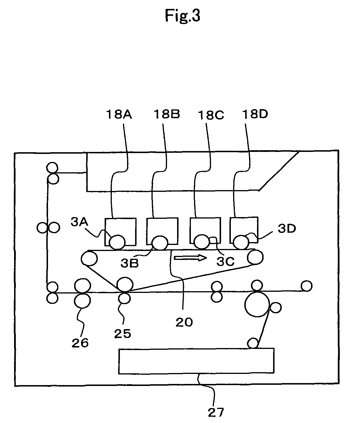
An image forming apparatus having a touchdown-development type developing apparatus, in which a toner collecting roller that collects scattered toner suspended in the vicinity of a toner holding body and a two-component developer holding body is arranged on the downstream side in a rotational direction of the two-component developer holding body from a closest position of the two-component developer holding body and the toner holding body, and between the two-component developer holding body and the housing wall, and further, bias means that applies a bias voltage for collecting the scattered toner to the toner collecting roller, and image density sensing means for sensing a density of a toner image developed on the electrostatic latent image holding body surface or a toner image on a transfer body onto which the toner image developed on the electrostatic latent image holding body surface is transferred to control the bias voltage are provided.

Description

BACKGROUND OF THE INVENTION[0001]1. Field of the Invention[0002]The present invention relates to an image forming apparatus such as a copier, printer, facsimile, and a complex machine of them, and particularly to an image forming apparatus adapted such that a two-component developer, which charges a nonmagnetic toner using a magnetic carrier, is utilized to form a magnetic brush, the magnetic brush forms a toner thin layer on a developing roller, and the toner of the toner thin layer flies on an electrostatic latent image to develop the latent image.[0003]2. Description of Related Art[0004]Conventionally, in an electrographic image forming apparatus, a one-component developing method and a two-component developing method have been known as a developing method using a dry toner.[0005]In the one-component developing method, since no carrier is contained, an electrostatic latent image of a photoreceptor is not disturbed by the magnetic brush formed of the carrier and the toner, which i...

Claims


Application Information

Patent Timeline
Patent Type & Authority Patents(United States)
IPC IPC(8): G03G15/00G03G15/09G03G15/08G03G15/06
CPCG03G15/0907G03G15/0808
Inventor FUJISHIMA, MASASHIWATANABE, AKIHIROUEMURA, SAYOMORI, YUKIHIRO
Owner KYOCERA DOCUMENT SOLUTIONS INC
Learn More