Container cleaning machine

a container and cleaning machine technology, applied in the direction of vacuum cleaners, household cleaners, tableware washing/rinsing machines, etc., can solve the problems of less efficient and effective arrangement of cleaning containers, and achieve the effect of facilitating placement and movement and maximising cleaning efficiency

Inactive Publication Date: 2011-05-10
RIGGS MARK AARON
View PDF11 Cites 0 Cited by
  • Summary
  • Abstract
  • Description
  • Claims
  • Application Information

AI Technical Summary

Benefits of technology

More particularly the present invention relates to an apparatus for cleaning a substantially air-tight reusable container having an open side with edges that can sit flush on a flat surface containing a plurality of openings positioned to fit inside the open side of the container when the container is placed with the open side flush on the flat surface. The openings include a central port or opening connected to a vacuum or low pressure source and a plurality of other ports or openings positioned evenly in a circular pattern outside the central port and connected to an air compressor or high pressure source. A manual or electronic switch is employed to simultaneously activate the high and low pressure sources and thereby create movement of air inside the container to loosen the debris in the container and exhaust it through the central port. The capability of simultaneous activation of high and low pressure and the use of a flat surface are essential features of the present invention to make the cleaning operation more efficient and effective. Such activation is preferably accomplished by use of a sensor that responds to the presence and / or movement of the container on the flat surface.
The most preferred features of the present invention are a solid flat surface, openings in the surface comprising a centrally located hole or opening connected to a low pressure source and a plurality of smaller holes or openings equally distributed in a circle outside the center opening and connected to a high pressure source, and a switch wired to activate the high and low pressure air substantially simultaneously into the open top of inverted open topped containers placed on the surface over the holes. The flat surface facilitates placement and movement of the open top of a container over the holes to remove debris from inside the container by simultaneous delivery of high and low pressure into the container and subsequent removal of the container from the flat surface. A motion sensor located in close proximity to the air holes but no further from the center hole that reacts to the presence of a container over the holes is preferred over a manual switch. This frees the operator to move the container over the holes to achieve maximum cleaning efficiency, especially for large containers having a correspondingly larger open top.

Problems solved by technology

That arrangement proved less efficient and effective in cleaning containers as will be shown hereinafter.

Method used


Image

  • Container cleaning machine
  • Container cleaning machine
  • Container cleaning machine

Examples


Embodiment Construction

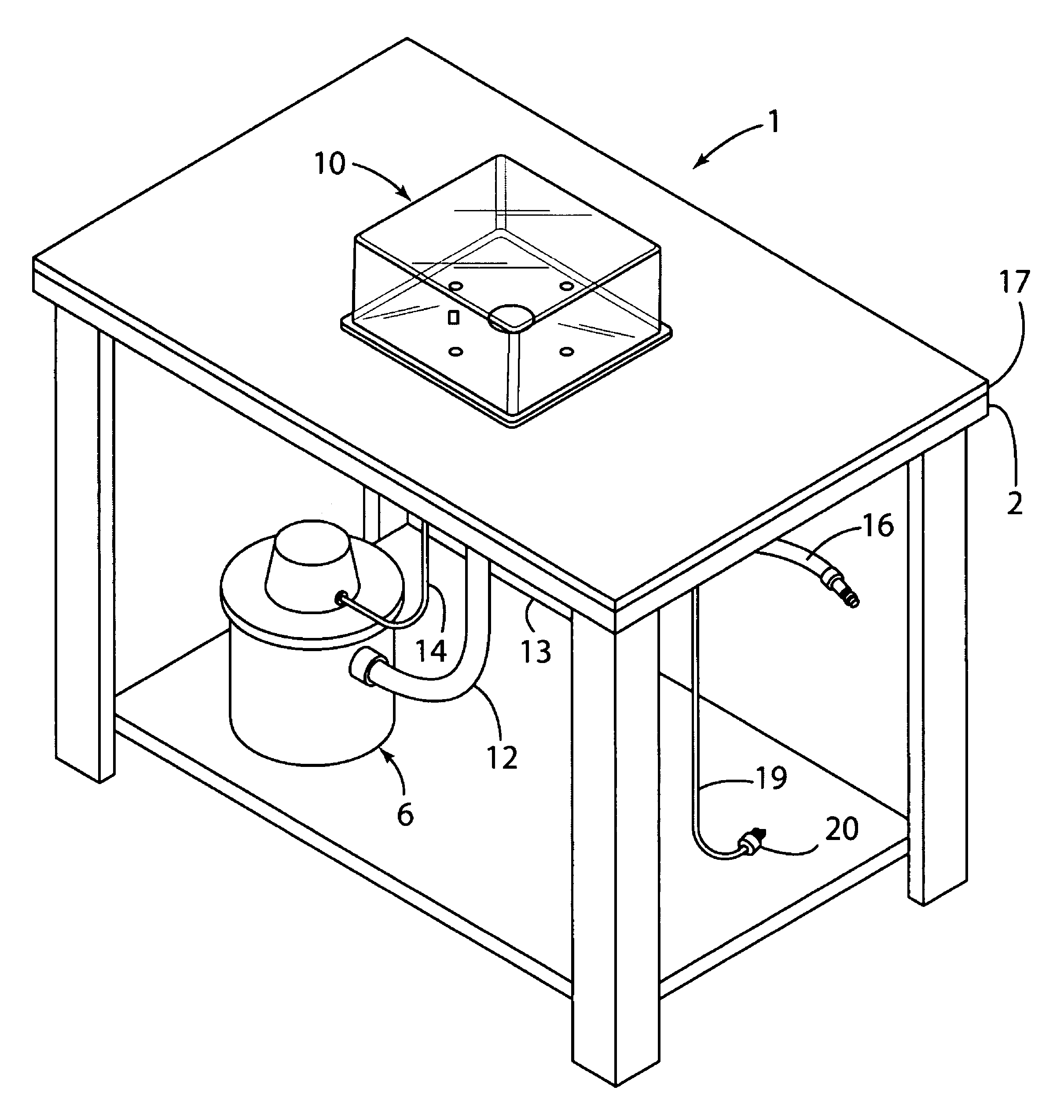
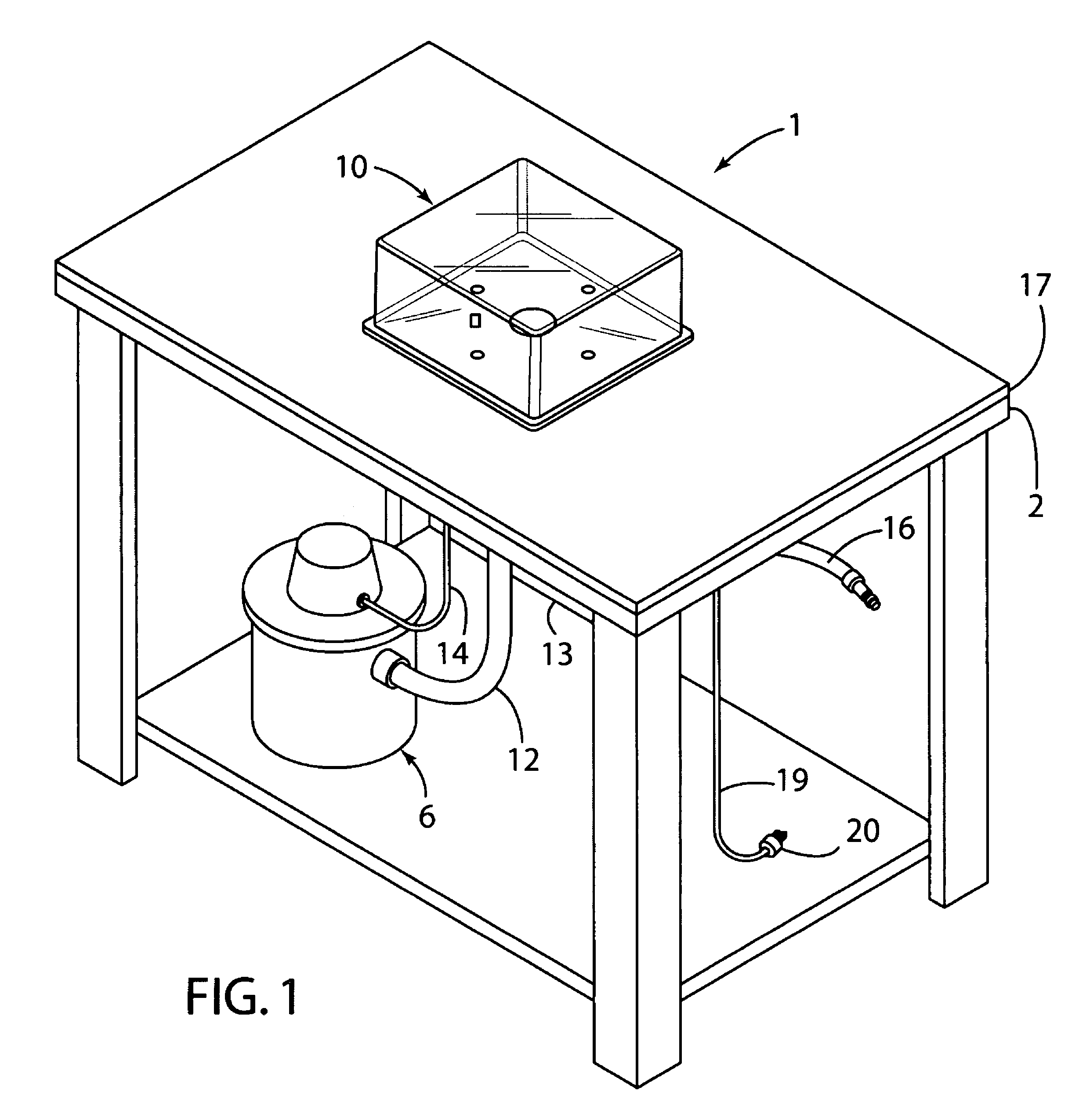
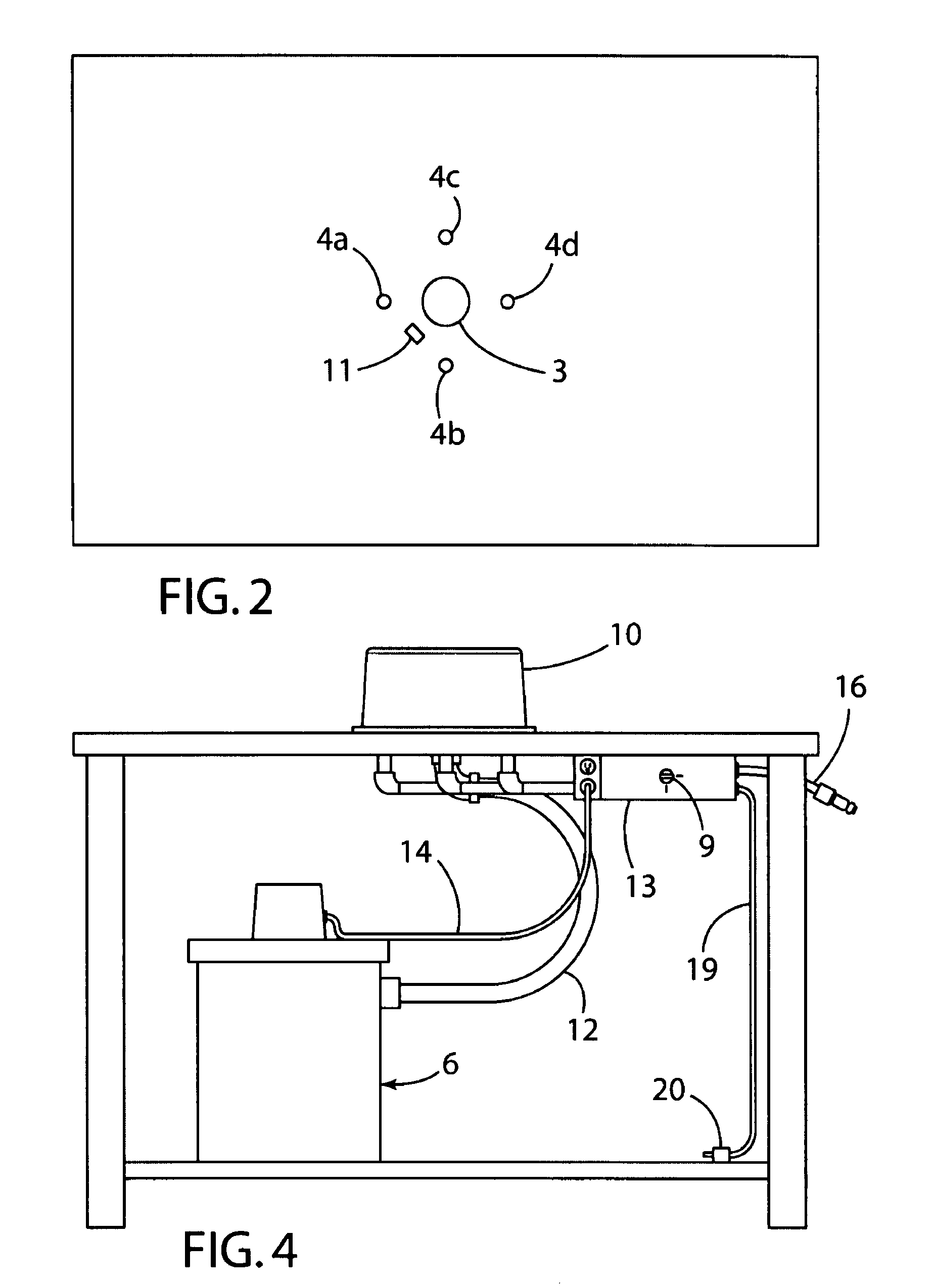
FIG. 1 shows the preferred embodiment of the invention that includes a table 1 with a top 2, a large centrally located hole 3 and four smaller holes 4a-d distributed evenly in a 2¾ inch radius circle around the center hole 3, all five holes being centered on the table top 2. The table top 2 is 48 inches long and 34 inches wide. The center hole 3 is 1¼ inches in diameter and the smaller holes 4a-d are ¼ inches in diameter. These dimensions are not critical to the invention. The pattern of a central hole 3 to accommodate a source for low pressure air and outer holes 4a-d circling the center hole 3 is a preferred but not an essential part of the invention. The top 2 is covered by ¼ inch thick plastic cover 17 (sold under the trademark Lexan) with the same holes and dimensions as the table top 2. The plastic cover 17 is added to provide a smoother surface on the table 1 but is not essential to the invention. A 1×¼ inch rectangular hole 11 between two of the smaller holes 4a and 4b at th...


PUM


Abstract

A container cleaning apparatus comprising a table having holes in the top surface suitably arranged to deliver compressed air and a vacuum substantially simultaneously into the open top of an inverted reusable container placed on the table top and thereby remove debris from the inside of the container.

Description

FIELD OF THE INVENTIONThe present invention relates to a machine for cleaning containers, especially reusable containers. Manufacturers and warehousemen often use containers repeatedly to save money. Some type of machine or method for cleaning such containers is therefore necessary.BACKGROUND OF THE INVENTIONIndustrial facilities often use containers or totes for transporting products or loose materials from one location to another. Repeated use of these containers makes their use more economical. Therefore there is a need for removing debris such as small particles or shavings of metal, plastic, paper and foam that commonly accumulate in these containers after each use.U.S. Pat. No. 5,279,017 describes a method and apparatus for extracting particles from such containers. The apparatus described includes two caps that close in succession over the open top of containers passing beneath the caps on a conveyer. The first cap supplies high pressure into the containers to loosen particle...

Claims


Application Information

Patent Timeline
Patent Type & Authority Patents(United States)
IPC IPC(8): A47L5/14
CPCB08B5/02B08B9/093B08B9/08B08B5/04
Inventor RIGGS, MARK AARON
Owner RIGGS MARK AARON
Why Eureka
Try Eureka