Underwater power station and method for operating an underwater power station

a power station and underwater technology, applied in the direction of mechanical equipment, electric generator control, machines/engines, etc., can solve the problems of not being able to avoid certain shading effects of the support structure (tower shadow), unable to make any passive readjustment with a changeable inflow direction of current-side runners, etc., to achieve efficient and effective operation of underwater power stations

Inactive Publication Date: 2010-09-14
VOITH PATENT GMBH
View PDF13 Cites 6 Cited by
  • Summary
  • Abstract
  • Description
  • Claims
  • Application Information

AI Technical Summary

Benefits of technology

[0013]The present invention provides a method and apparatus for efficiently and effectively operating an underwater power plant, for example, a power plant standing freely in an ocean current, dealing in particularly with a method and apparatus for adjustment to the change in the inflow direction caused by the tide and for moving towards a maintenance position.
[0019]According to a third embodiment of the present invention, a third position can be provided in the area of the apex which is approached, for example, for service purposes. When a rotor-like turbine is used, for example, it will have in this position a perpendicularly positioned hub and a horizontal orientation of the rotor blades. A separation from the spacer element can be made from this position, for example, in order to enable a lifting of the rotor-like turbine to the surface of the water. Alternatively, the pivoting movement can be performed in the vertical plane in such a way that the turbine performs a semi-circle through the bottom apex. The advantage of such a downward pivoting movement is that the turbine can be pivoted out of a shipping channel, for example, for the passage of a ship with a high draught when necessary.
[0021]According to a fifth embodiment of the present invention, the transition between the first position and the second position of the turbine occurs, in each case, as a reciprocating movement and not as a full circle, in order to avoid twisting of connecting cables between an electric machine integrated in the spacer element and the further guidance of the cable connection in the support structure. This fact is relevant both for lee-side runners as well as current-side runners, so that even in the case of a lee-side runner, a controlled, active forward and backward movement by means of the method and apparatus in accordance with the present invention is possible instead of passive adjustment to the current. It is necessary for the reciprocating movement between the first position and the second position to reverse the direction of force by the turbine, which is achieved by the respectively opposite rotation of the turbine.
[0023]According to a seventh embodiment of the present invention, a braking apparatus with effect on the pivoting movement is provided. In the simplest of cases, this will be a brake in the pivot joint. The advantage of such a braking apparatus is that the pivoting movement can be advantageously controlled, so that the pivoting movement caused by the driven turbine and the lever arm arrangement of the spacer element according to the present invention will not only be counteracted by inertia and current forces, but that the pivoting movement is substantially performed against a braking moment to be controlled or regulated. It is, therefore, possible to pass through the end phase before the new desired position is reached in an especially smooth manner.

Problems solved by technology

The disadvantageous aspect is, however, that a large circle of motion cannot be avoided in most cases and, therefore, such systems cannot be combined efficiently into an energy park with several underwater power stations.
The disadvantageous aspect in a lee-side runner is that a certain shading effect by the support structure (tower shadow) cannot be avoided.
However, there is no possibility for a current-side runner to make any passive readjustment with a changeable direction of inflow, so that the position of the turbine to the direction of the current needs to be guided actively.
These are disadvantageous in view of the desire to produce underwater power stations requiring as little maintenance as possible because the additionally used gear and motor components lead to an increased probability for failure.
Accordingly, there is higher expenditure for regular inspections, which themselves pose difficulties in view of the limited accessibility of underwater power stations.
Although this measure allows omitting the rotation of the entire turbine into the current, the problem of increased need for maintenance will be shifted due to additional moved components and the actuators associated with the same to a turbine-side apparatus, which is also susceptible to errors.
Accordingly, the turbine will assume a certain relative position to the ambient current for initiating an inspection, so that even in this case the problems as explained above will occur.

Method used


Image

  • Underwater power station and method for operating an underwater power station
  • Underwater power station and method for operating an underwater power station
  • Underwater power station and method for operating an underwater power station

Examples


Embodiment Construction

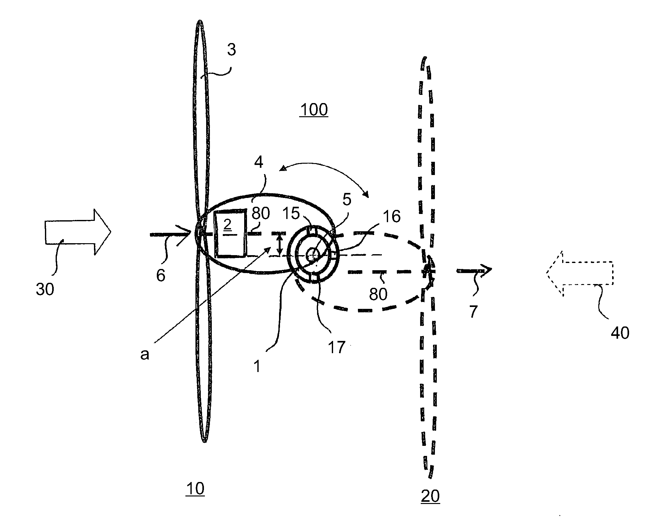
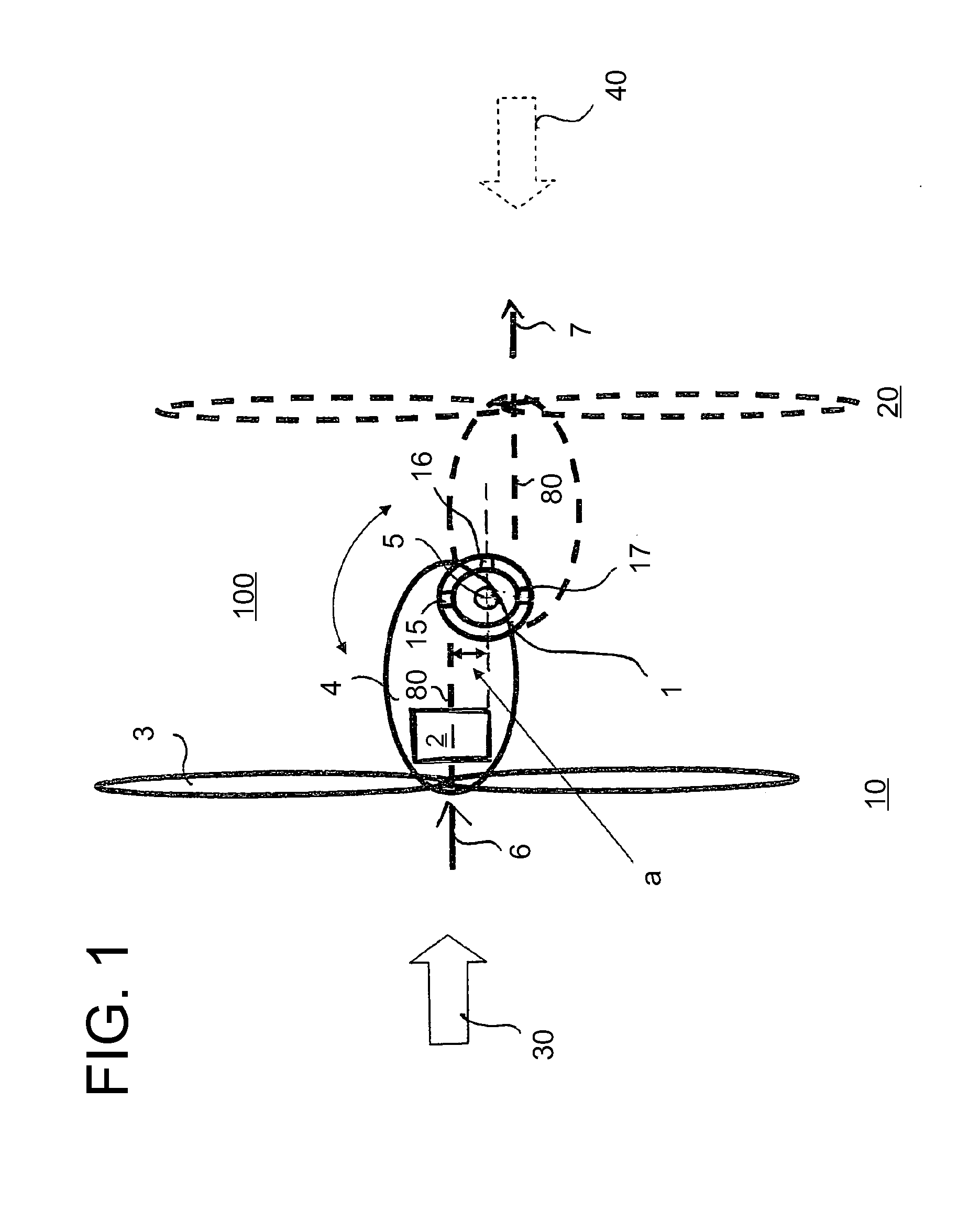
[0036]Referring now to the drawings, and more particularly to FIG. 4, there is shown a generic, free-standing underwater power station in a schematic simplified view, including support structure 1 in the form of a support pillar and a foundation anchored to floor 60 of the ocean. Support structures 1 can also be arranged in a different way for the present application, e.g. as support grating structures or as anchored floating units, insofar as they are suitable to support pivoting turbine 3 with a certain distance from a linkage point.

[0037]FIG. 4 further illustrates first inflow direction 30 for turbine 3. Opposite of first inflow direction 30 there is a unit of turbine 3 and spacer element 4 for the illustrated operational situation in the, for example, current-side position for generator operation of the underwater power station.

[0038]A rotor-like structure with two propeller blades is shown in FIG. 4 as turbine 3. It is connected, for example, in a rigid manner with a rotor hub....


PUM


Abstract

A method an apparatus for operating an underwater power plant including a support structure; at least one turbine; at least one electric machine configured to be operated as a generator or a motor, the at least one electric machine being in an at least indirect drive connection with the at least one turbine and the at least one electric machine in a motive operation is configured to drive the at least one turbine to produce a propulsive power; and a spacer element between the at least one turbine and the support structure, wherein the at least one turbine is attached to one end of the spacer element and a pivot joint to the support structure is attached to an opposing end of the spacer element, a linkage point of the pivot joint having an eccentricity which is a lateral offset to a force action line of the propulsive power.

Description

CROSS REFERENCE TO RELATED APPLICATIONS[0001]This is a continuation of PCT application No. PCT / EP2008 / 001002, entitled “UNDERWATER POWER STATION AND METHOD FOR OPERATING AN UNDERWATER POWER STATION”, filed Feb. 9, 2008, which is incorporated herein by reference.BACKGROUND OF THE INVENTION[0002]1. Field of the Invention[0003]The present invention relates to a method and apparatus for operating an underwater power plant, especially a power plant standing freely in an ocean current, dealing especially with a method and apparatus for adjustment to the change in the inflow direction caused by the tide and for moving towards a maintenance position.[0004]2. Description of the Related Art[0005]Free-standing, immersed power generation plants can be used economically from flow velocities of 2 to 2.5 meters per second. Water turbines with a propeller-like structure, for example, are fastened for this purpose to support structures for taking up kinetic energy from the ambient current. Depending...

Claims


Application Information

Patent Timeline
Patent Type & Authority Patents(United States)
IPC IPC(8): F03B13/10
CPCF03B13/264F03B17/061E02B2017/0091Y02E10/38F05B2240/97Y02E10/28Y02E10/30F03B17/06F03B13/26F03B15/04Y02E10/20
Inventor PERNER, NORMANHOLSTEIN, BENJAMIN
Owner VOITH PATENT GMBH
Why Eureka
Try Eureka