System for ventilating a combustion chamber wall

a technology for combustion chambers and ventilation systems, which is applied in the direction of efficient propulsion technologies, machines/engines, light and heating apparatus, etc., can solve the problems of reducing the performance of turbomachines, and achieve the effect of improving the performance of these ventilation systems

Active Publication Date: 2011-05-10
SN DETUDE & DE CONSTR DE MOTEURS DAVIATION S N E C M A
View PDF8 Cites 3 Cited by
  • Summary
  • Abstract
  • Description
  • Claims
  • Application Information

AI Technical Summary

Benefits of technology

[0008]The case according to the invention ensures a stable air flow, without separation and with minimal pressure losses along the internal wall of the combustion chamber, which allows an optimal supply of the air injection means and of the primary and dilution orifices of the internal wall of the chamber.
[0015]The case is advantageously formed of two half-shells juxtaposed transversely, which makes the case easier to install in the turbomachine. A cylindrical ring may be engaged axially and attached for example by welding to the downstream cylindrical rim of the case in order to keep the two half-shells assembled.

Problems solved by technology

The air that travels round the chamber passing between the latter and the end-piece of the diffuser is not guided and is subjected to turbulence, separations of flow and considerable pressure losses that reduce the performance of the turbomachine.

Method used


Image

  • System for ventilating a combustion chamber wall
  • System for ventilating a combustion chamber wall
  • System for ventilating a combustion chamber wall

Examples


Embodiment Construction

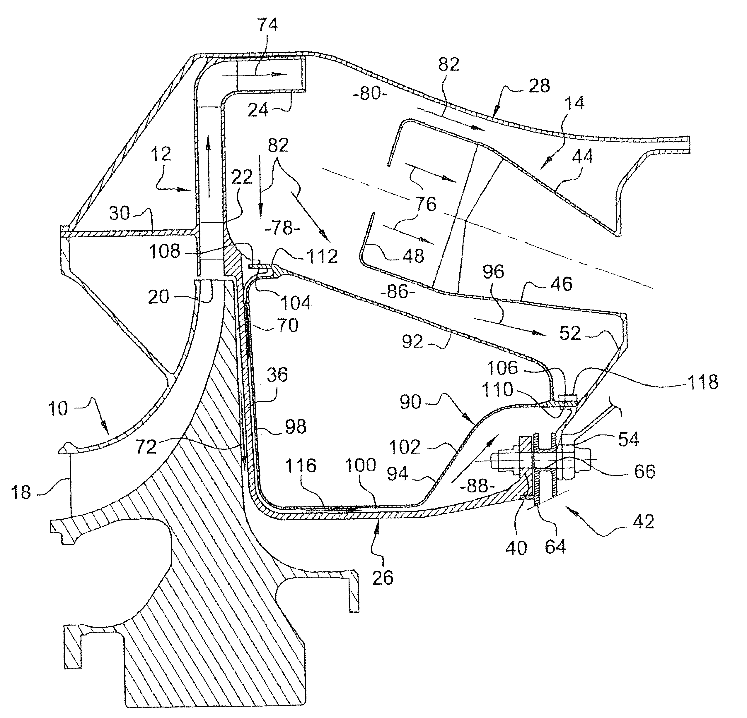
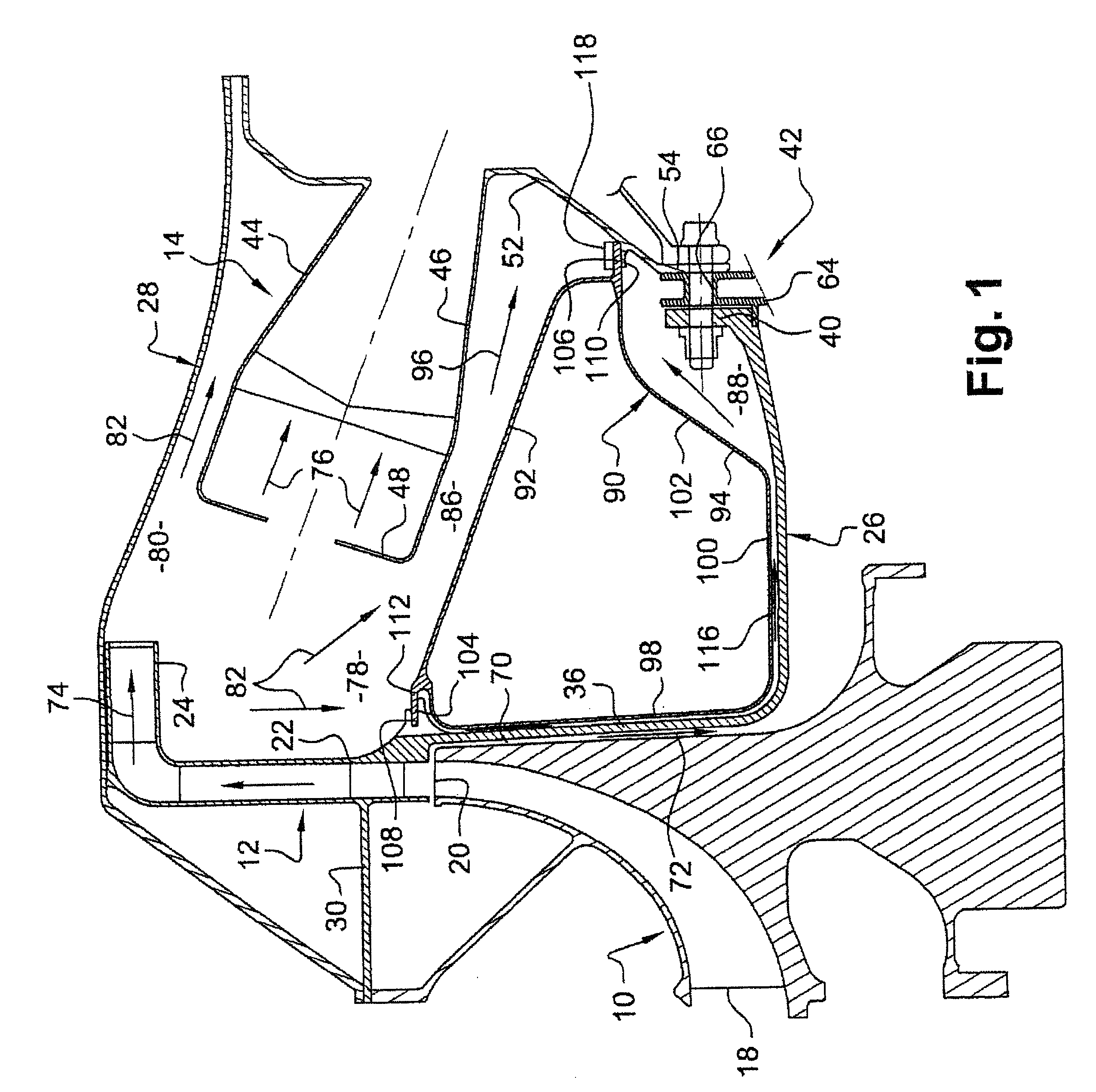
[0023]Reference is made first to FIG. 1 which represents a portion of a turbomachine, such as an aircraft turbojet or turboprop, comprising, from upstream to downstream, in the direction of flow of the gases inside the turbomachine, a centrifugal compressor 10, a diffuser 12 and a combustion chamber 14.

[0024]The inlet 18 of the centrifugal compressor 10 is oriented upstream, substantially parallel to the axis of the turbomachine, and its outlet 20 is oriented outward, substantially perpendicularly to the axis of the turbomachine, and is aligned with a radial portion 22 of the diffuser 12. The diffuser has a shape that is generally bent at 90° and comprises an axial outlet portion 24 that is connected to the radial portion 22 and that extends along the external casing 28 and opens at its radially downstream end on the outside of the inlet of the combustion chamber 14.

[0025]The diffuser 12 is supported by the external casing 28 which externally surrounds the compressor 10, the diffuse...


PUM


Abstract

A system for ventilating a combustion chamber wall in a turbomachine is disclosed. The system includes a centrifugal compressor, a diffuser, a combustion chamber, and an annular case arranged radially between the combustion chamber and a downstream end-piece of the diffuser. The annular case includes a radially external wall for the guidance of an air flow coming out of the diffuser, and a radially internal wall delimiting with the end-piece of the diffuser a channel for the air coming out of the diffuser to pass through.

Description

[0001]The present invention relates to a system for ventilating a combustion chamber wall in a turbomachine comprising a centrifugal compressor and a diffuser supplying an annular combustion chamber with air.BACKGROUND OF THE INVENTION[0002]In a conventional manner, the annular combustion chamber of the turbomachine is situated in an annular space delimited by an external casing, this casing supporting the diffuser which comprises an annular end-piece which extends downstream and along the rotor or impeller of the centrifugal compressor.DESCRIPTION OF THE PRIOR ART[0003]The air coming out of the diffuser is intended, primarily, to enter the combustion chamber and be mixed with fuel and then burnt, and secondarily, to travel round the combustion chamber and to supply primary and dilution orifices of the chamber and of the air injection means for ventilating and / or cooling a turbine situated downstream of the combustion chamber (see for example document U.S. Pat. No. 5,555,721).[0004]...

Claims


Application Information

Patent Timeline
Patent Type & Authority Patents(United States)
IPC IPC(8): F02C7/22
CPCF01D5/082F01D25/12F02C3/08F02C3/14F23R3/26F02C7/18F05D2240/14Y02T50/676F05D2250/182Y02T50/60
Inventor BRUNET, ANTOINE ROBERT ALAINCOMMARET, PATRICE ANDREHERNANDEZ, DIDIER HIPPOLYTELOCATELLI, DAVID
Owner SN DETUDE & DE CONSTR DE MOTEURS DAVIATION S N E C M A
Why Eureka
Try Eureka