Plasma arc torch providing angular shield flow injection

a technology of angular shield and arc torch, which is applied in the field of plasma arc torch, can solve the problems of degrading cutting, piercing or marking performance, plasma gas having difficulty cooling the tip of the nozzle, and less protection from reflecting slag, so as to achieve stable ionized plasma gas flow, effective cooling, and effective cooling

Active Publication Date: 2007-01-11
HYPERTHERM INC
View PDF20 Cites 13 Cited by
  • Summary
  • Abstract
  • Description
  • Claims
  • Application Information

AI Technical Summary

Benefits of technology

[0008] The invention, in one embodiment, remedies the deficiencies of the prior art by providing a plasma arc torch that provides effective cooling of the torch's nozzle and protection from slag reflection while also providing stable plasma gas flow. The plasma arc torch of the present invention can be used to cut, pierce and / or mark metallic materials. The torch includes a torch body having a nozzle mounted relative to an electrode in the body to define a plasma chamber. The torch body includes a plasma flow path for directing a plasma gas to the plasma chamber. The torch also includes a shield attached to the torch body. The nozzle, electrode, and shield are consumable parts that wear out and require periodic replacement. Thus, these parts are detachable and, in some embodiments, re-attachable so that these parts can be easily removed, inspected for wear, and replaced.
[0015] In another aspect, the invention features a-nozzle for a plasma arc torch. The nozzle includes a nozzle body including a substantially hollow interior and a substantially conical exterior portion having a nozzle half-cone angle. The nozzle body defines an exit orifice disposed on an end face of the nozzle. The exit orifice is defined by an orifice diameter (D), an orifice length (L), and a nozzle end face diameter (φ1), wherein the nozzle half-cone angle, a L to D ratio, and a φ1 to D ratio are selected to provide the plasma arc torch with effective cooling of the nozzle, protection from slag reflection, and a stable ionized plasma gas flow.
[0016] In another aspect, the invention features a torch tip for a plasma arc torch. The torch tip has a longitudinal axis and includes a nozzle and a shield. The nozzle includes a nozzle body including a substantially hollow interior and a substantially conical exterior portion having a nozzle half-cone angle. The nozzle body defines an exit orifice disposed on an end face of the nozzle. The exit orifice is defined by an orifice diameter (D), an orifice length (L), and a nozzle end face diameter (φ1). The shield includes a shield body defining a shield exit orifice diameter (φ2). The shield body includes a substantially conical interior portion having a shield half-cone angle, which is substantially equal to the nozzle half-cone angle. The shield is mounted in a spaced relation to the nozzle relative to the longitudinal axis such that a fluid passageway is formed in a space between the substantially conical interior portion of the shield and the substantially conical exterior portion of the nozzle. The nozzle half-cone angle, a L to D ratio, and a φ2 to φ1 ratio are selected to provide the plasma arc torch with effective cooling of the nozzle, protection from slag reflection, and a stable ionized plasma gas flow.
[0017] In another aspect, the invention features a plasma arc torch including a longitudinal axis. The plasma arc torch includes a plasma arc torch body, a nozzle, and a shield. The plasma arc torch body includes a plasma flow path for directing a plasma gas to a plasma chamber in which a plasma arc is formed. The nozzle is mounted relative to an electrode in the plasma torch body to define a plasma chamber. The nozzle include a nozzle body including a substantially hollow interior and a substantially conical exterior portion having a nozzle half-cone angle. The nozzle body defines an exit orifice disposed on an end face of the nozzle. The exit orifice is defined by an orifice diameter (D), an orifice length (L), and a nozzle end face diameter (φ1). The shield includes a shield body defining a shield exit orifice diameter (φ2). The shield body includes a substantially conical interior portion having a shield half-cone angle, which is substantially equal to the nozzle half-cone angle. The shield is mounted in a spaced relation to the nozzle relative to the longitudinal axis such that a fluid passageway is formed in a space between the substantially conical interior portion of the shield and the substantially conical exterior portion of the nozzle. The nozzle half-cone angle, a L to D ratio, and a φ2 to φ1 ratio are selected to provide the plasma arc torch with effective cooling of the nozzle, protection from slag reflection, and a stable ionized plasma gas flow.
[0018] In another aspect, the invention features a consumable for a plasma arc torch. The consumable includes a first passageway for an ionized plasma fluid and a second passageway for a shield fluid. The first passageway is parallel to a longitudinal axis of the consumable. The first passageway includes a first exit orifice for ejecting the ionized plasma fluid. The second passageway includes a second exit orifice and is disposed at an angle to the first passageway such that the shield fluid impinges the plasma fluid after ejection at an angle selected to provide the plasma arc torch with effective cooling of a portion of the consumable, protection from slag reflection, and a stable ionized plasma fluid flow.

Problems solved by technology

As a result of the impingement, the ionized plasma gas flow can be disrupted (e.g., generating instabilities in the plasma gas flow), which may lead to degraded cutting, piercing, or marking performance.
However, in general, plasma arc torches that have substantially columnar flow of the shield gas and the plasma gas have difficulty cooling the tip of the nozzle and provide less protection from reflecting slag during cutting than plasma arc torches which use 90 degree impinging shield gas flow injection.

Method used


Image

  • Plasma arc torch providing angular shield flow injection
  • Plasma arc torch providing angular shield flow injection
  • Plasma arc torch providing angular shield flow injection

Examples


example 2

[0044] A torch tip having a substantially conical exterior nozzle portion and a substantially conical interior shield portion was modeled using thermal analysis and the results were compared to a model of a conventional torch tip that provided columnar flow. Referring to FIGS. 7 and 8, FIG. 7 shows the thermal analysis results for the torch tip that provided columnar flow and FIG. 8 shows the thermal analysis results for the torch tip that provides angular flow of 42.5 degrees. Both the prior art torch tip and the torch tip of in accordance with the invention had a L / D of 2.6, a φ1 / D of 2.1, and a φ2 / φ1 of 1.03.

[0045] As shown in FIG. 7, the torch tip having columnar flow experiences a maximum temperature of 996 degrees C., whereas the torch tip providing angular flow (FIG. 8) experiences a maximum operating temper of 696 degrees C. under equal heat loading. As a result, the torch tip of the present invention provides better conduction of heat away from the nozzle during use. Thus,...

example 3

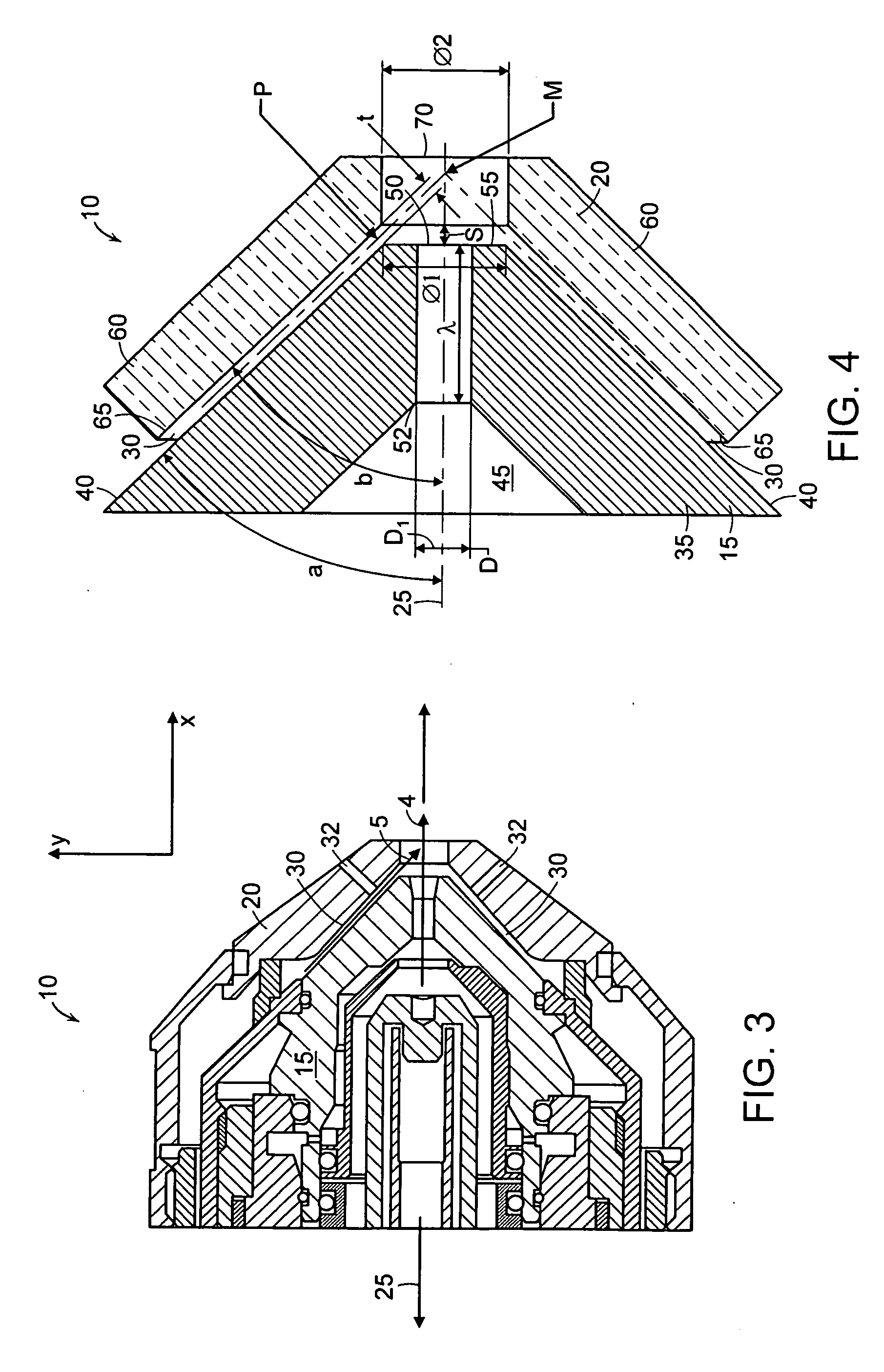
[0046] A torch tip having a substantially conical exterior nozzle portion and a substantially conical interior shield portion can be used to cut ¾ inch mild steel on a dross-free speed of up to 100 ipm. Both the substantially conical exterior nozzle portion and the substantially conical interior shield portion had a half-cone angle of 30 degrees. Each of the shield and the nozzle are machined from copper and include o-rings to secure the torch tip to the plasma arc torch. The shield has twelve vent holes disposed therein to provide additional cooling.

[0047] The shield and the nozzle are mounted with respect to each other along the longitudinal axis at a distance of 0.04 inches to form a passageway having a thickness of 0.020. The velocity of the shield gas (air) as it exited the passageway at point P is 2,500 inches per second. The exit orifice of the nozzle has a length L of 0.234 inches, a diameter D of 0.0867 inches, and a nozzle end face diameter φ1 of 0.18 inches. As a result,...

example 4

[0048] A torch tip having a substantially conical exterior nozzle portion and a substantially conical interior shield portion can be used to cut ¾ inch mild steel on a dross-free speed of up to 100 ipm. Both the substantially conical exterior nozzle portion and the substantially conical interior shield portion had a half-cone angle of 47 degrees. Each of the shield and the nozzle are machined from copper and include o-rings to secure the torch tip to the plasma arc torch. The shield has twelve vent holes disposed therein to provide additional cooling.

[0049] The shield and the nozzle are mounted with respect to each other along the longitudinal axis at a distance of 0.03 inches to form a passageway having a thickness of 0.022. The velocity of the shield gas (air) as it exited the passageway at point P is 5,000 inches per second. The exit orifice of the nozzle has a length L of 0.234 inches, a diameter D of 0.0867 inches, and a nozzle end face diameter φ1 of 0.208 inches. As a result...


PUM

PropertyMeasurementUnit
half-cone angleaaaaaaaaaa
velocityaaaaaaaaaa

Abstract

Plasma arc torches described herein include a torch tip with an improved nozzle that provides angular shield flow injection. In particular, the nozzle provides angular / conical impingement of a fluid (e.g., a shield gas) on an ionized plasma gas flowing through a plasma arc torch. Some of the torch tips described herein include a nozzle with a conical external shape combined with a shield with complementing internal geometry to form the angular fluid flow. As a result, a plasma arc torch including the improved nozzle have the benefits of a stabilized ionized plasma gas flow together with enhanced nozzle cooling and protection from reflecting slag during torch use.

Description

RELATED APPLICATIONS [0001] This application claims the benefit of the filing date of U.S. Provisional Patent Application Ser. No. 60 / 672,777, filed on Apr. 19, 2005, entitled “Plasma Arc Torch Providing Angular Shield Flow Injection” by Duan et al., the entirety of which is incorporated herein by reference.FIELD OF THE INVENTION [0002] The invention generally relates to plasma arc torches used for cutting, piercing, and marking metal, and more particularly to plasma arc torches that provide angular (e.g., conical) shield flow injection to a plasma arc. BACKGROUND OF THE INVENTION [0003] Plasma arc torches are widely used in the cutting, piercing, and / or marking of metallic materials (e.g., elemental metals, metal alloys). A plasma arc torch generally includes an electrode mounted within a body of the torch (i.e., a torch body), a nozzle having an exit orifice also mounted within the torch body, electrical connections, fluid passageways for cooling fluids, shielding fluids, and arc ...

Claims


Application Information

Patent Timeline
Patent Type & Authority Applications(United States)
IPC IPC(8): B23K9/00B23K9/02
CPCH05H1/34H05H2001/3457H05H2001/3484H05H2001/3478H05H1/3457H05H1/3484H05H1/3478
Inventor DUAN, ZHENGLIEBOLD, STEPHENBRANDT, AARON
Owner HYPERTHERM INC
Why Eureka
Try Eureka