Internal combustion engine air intake structure
a technology of air intake and combustion engine, which is applied in the direction of combustion-air/fuel-air treatment, machines/engines, mechanical equipment, etc., can solve the problems of difficult to obtain gas flows of various strengths, the air intake control valve cannot be used in one of two different valve opening states, and the inability to produce stable swirl flow, etc., to achieve stable gas flow and stable swirl flow
- Summary
- Abstract
- Description
- Claims
- Application Information
AI Technical Summary
Benefits of technology
Problems solved by technology
Method used
Image
Examples
first embodiment
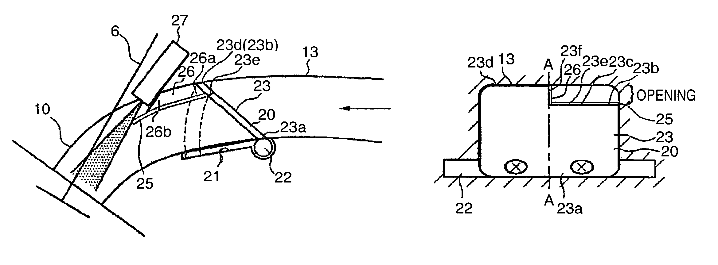
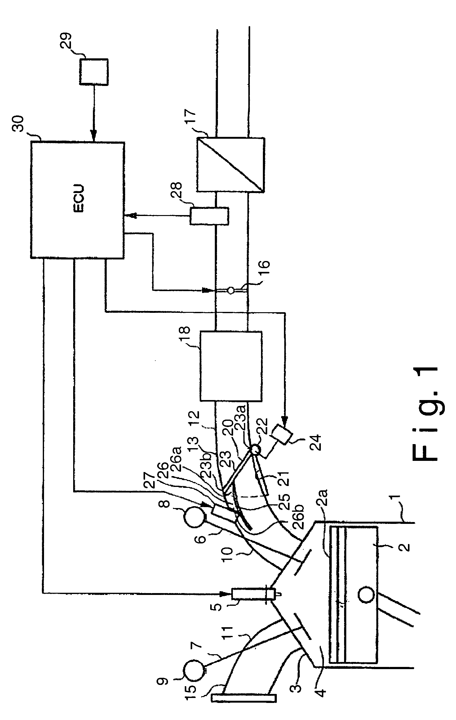
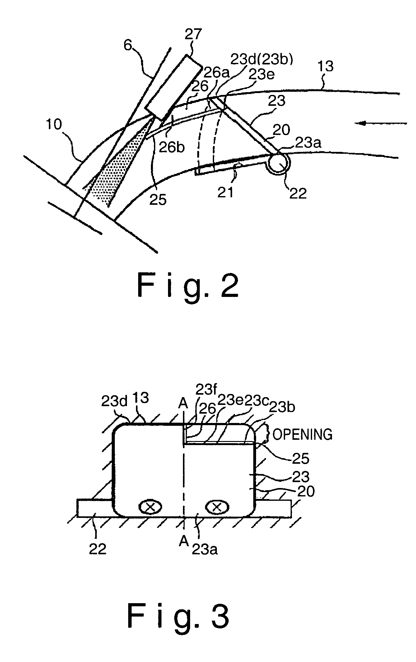
[0034]Referring initially to FIG. 1, a portion of an internal combustion engine is schematically illustrated that is configured with an air intake structure in accordance with a first embodiment of the present invention. The internal combustion engine basically includes a plurality of (e.g., four) cylinders 1 (only one shown in figure) with a piston 2 arranged inside of each of the cylinders 1 to reciprocate in a conventional manner. The cylinders 1 are formed in an engine block that has a cylinder head 3 mounted to overlie each of the cylinders 1. Thus, a top surface 2a of each of the pistons 2 and a portion of the cylinder head 3 above each of the cylinders 1 form a combustion chamber 4. A spark plug 5 is arranged in the cylinder head 3 above each of the combustion chambers 4.
[0035]Two intake valves 6 and two exhaust valves 7 are arranged in each of the combustion chambers 4. The intake valves 6 and the exhaust valves 7 are opened and closed by a pair of valve operating mechanisms...
second embodiment
[0055]Referring now to FIGS. 4 and 5, an air intake structure is illustrated in accordance with a second embodiment. This air intake structure of the second embodiment replaces the air intake structure of the first embodiment that is shown in FIG. 1. In other words, the air intake structure of the second embodiment is installed in the internal combustion engine of FIG. 1. In view of the similarity between this embodiment and the prior embodiments, the parts of the second embodiment that are identical to the parts of the first embodiment will be given the same reference numerals as the parts of the prior embodiments. Moreover, the descriptions of the parts of the second embodiment that are identical to the parts of the first embodiments may be omitted for the sake of brevity.
[0056]In the second embodiment, one supplemental horizontal partitioning plate 25′ has been provided such that there are first and second horizontal partitioning plates 25 and 25′. Each of the first and second ho...
third embodiment
[0066]Referring now to FIGS. 6 and 7, an air intake structure is illustrated in accordance with a third embodiment. This air intake structure of the third embodiment replaces the air intake structure of the first embodiment that is shown in FIG. 1. In other words, the air intake structure of the third embodiment is installed in the internal combustion engine of FIG. 1. In view of the similarity between this embodiment and the prior embodiments, the parts of the third embodiment that are identical to the parts of the prior embodiments will be given the same reference numerals as the parts of the prior embodiments. Moreover, the descriptions of the parts of the third embodiment that are identical to the parts of the prior embodiments may be omitted for the sake of brevity.
[0067]As shown in FIGS. 6 and 7, the air intake structure can be provided with a plurality (four) of horizontal partitioning plates 25, 25′, 25″ and 25′″. Thus, the opening degree of the air intake control valve 20 c...
PUM
 Abstract
Description
Claims
Application Information
 - R&D
- Intellectual Property
- Life Sciences
- Materials
- Tech Scout
- Unparalleled Data Quality
- Higher Quality Content
- 60% Fewer Hallucinations
Browse by: Latest US Patents, China's latest patents, Technical Efficacy Thesaurus, Application Domain, Technology Topic, Popular Technical Reports.
© 2025 PatSnap. All rights reserved.Legal|Privacy policy|Modern Slavery Act Transparency Statement|Sitemap|About US| Contact US: help@patsnap.com


