Supplemental heat exchange for high pressure gas tank

a gas tank and heat exchange technology, applied in the direction of container filling under pressure, container discharging methods, packaged goods types, etc., can solve the problem of reducing the efficiency of internal heat exchangers to less than 100%, and achieve the effect of reducing the cost and weight of on-board cooling equipment, improving cooling capacity, and achieving heat exchange efficiency approaching 100%

Active Publication Date: 2011-05-10
HONDA MOTOR CO LTD
View PDF4 Cites 25 Cited by
  • Summary
  • Abstract
  • Description
  • Claims
  • Application Information

AI Technical Summary

Benefits of technology

[0005]It is an object of the invention to minimize tank heating and to increase the efficiency and refueling capacity of an on board fuel storage tank in a hydrogen powered motor vehicle. It is an object of the invention to minimize high pressure gas tank heating and to increase the efficiency and refueling capacity of an on board fuel storage tank in high pressure gas powered motor vehicles. It is an object of the invention to provide a system that can remove the compression heat resulting from refueling an on board tank during high pressure refueling. An avoidance of secondary gas cooling pretreatment and / or pressure overfill, a speedier refueling time, increased refueling efficiency, and an extension of overall vehicle range will result. Improved tank capacity per unit volume is achieved during refilling, particularly where nominal refill pressure is in the range of about 10,000 psi or greater for hydrogen and about 3,600 psi for CNG. Additionally, the system may be operated in the inverse to provide gas warming for use in cold climates and to compensate for gas cooling as the tank is depleted during driving. Vehicle range is thereby increased.SUMMARY OF THE INVENTION
[0007]The system described herein provides onboard cooling and reduces the cost and weight of on board cooling equipment. Cooling capacity is improved; continuous cooling is provided. Heat exchange efficiency approaches 100%. When there is an internal heat exchanger, the gas temperature in the heat exchanger is not perfectly equal to tank gas temperature, thus reducing internal heat exchanger efficiency to less than 100%. In the gas ejector system described herein, the gas flow cooling circuit, through an in situ device or a Venturi pump is interconnected with an external heat radiator or a vehicle sub cooling system such as an air conditioner, thereby collecting interior tank heat and radiating the absorbed heat into the ambient atmosphere or other system appropriate for the use, radiation, absorption, or disposal of the collected heat of high pressure refueling.

Problems solved by technology

When there is an internal heat exchanger, the gas temperature in the heat exchanger is not perfectly equal to tank gas temperature, thus reducing internal heat exchanger efficiency to less than 100%.

Method used


Image

  • Supplemental heat exchange for high pressure gas tank
  • Supplemental heat exchange for high pressure gas tank
  • Supplemental heat exchange for high pressure gas tank

Examples


example i

Supplemental Cooling

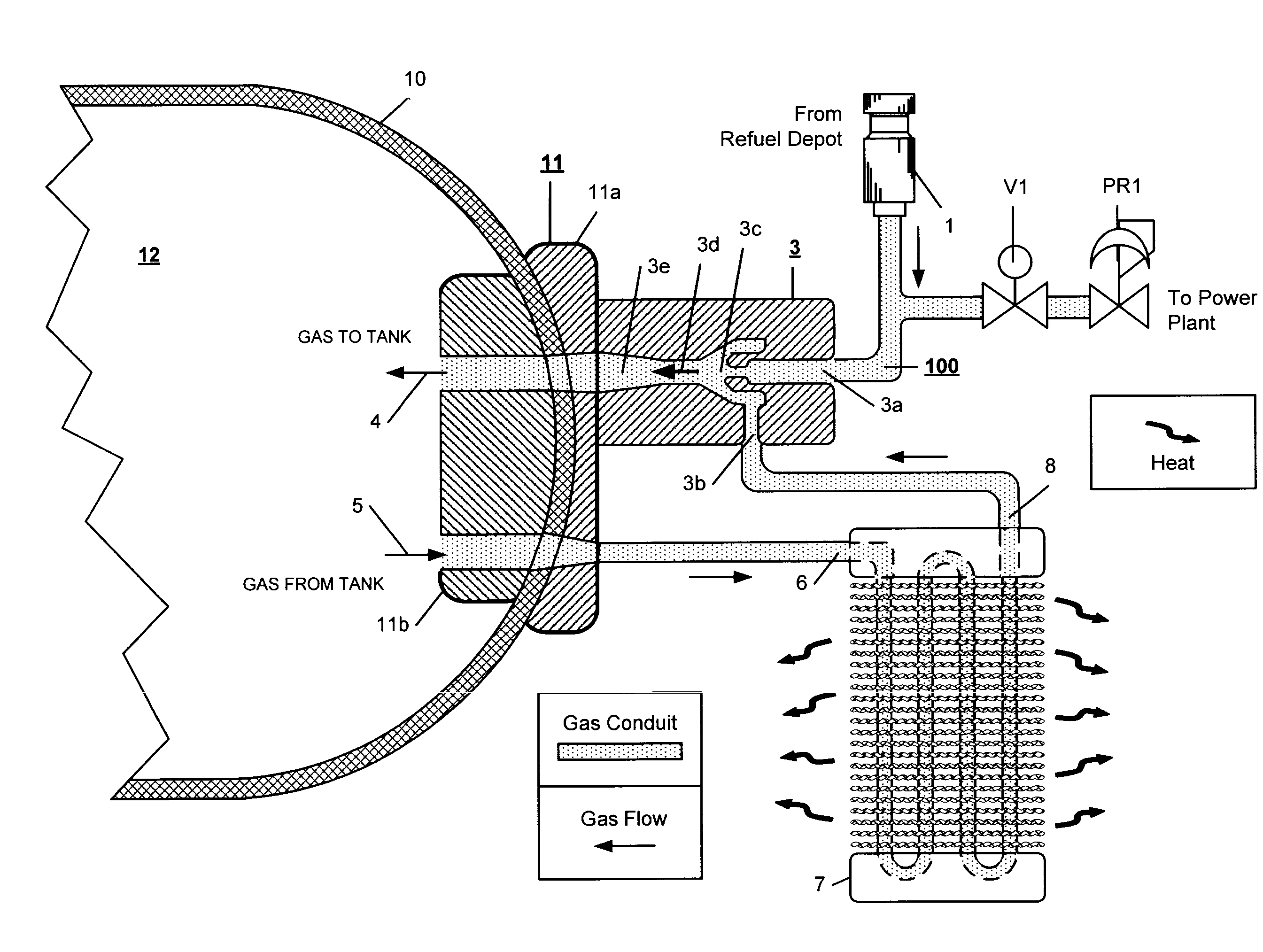
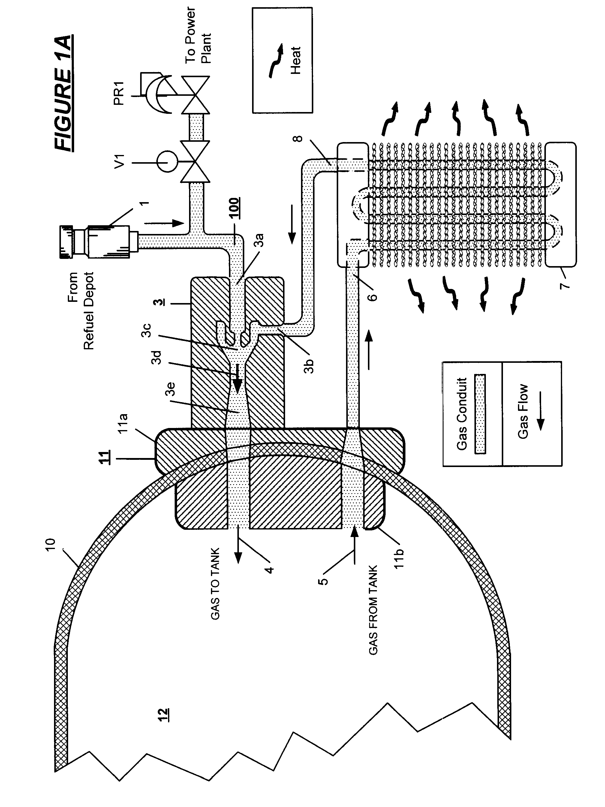
[0025]FIG. 3A illustrates the common disposition of first gas flow heat exchange loop passing through the in situ device HEX LOOP 1 and second gas flow heat exchange loop HEX LOOP 2 passing through the tank into the same external heat exchanger or radiator 35 where the heat may be dissipated in place or further cooled by a thermal interconnection with a main or sub vehicle cooling system trough an interconnection by inlet 36 and outlet 37. FIG. 3B shows the interconnection of HEX LOOP 1 and HEX LOOP 2 passing through radiator 35 interconnected with HEX LOOP 3, the vehicle power plant main or subsystem cooling loop. Radiator 35 is thermally interconnected with cooling fan 36.

[0026]FIG. 4A, FIG. 4B and FIG. 4C illustrate, in a vehicle application, the respective modes: refilling, driving and parking. In each FIG. 4A, FIG. 4B and FIG. 4C, a valve / gas flow switching and pressure regulator is embedded in each of the end port assemblies 20 and 21 as EV 20 and EV 21. He...

example ii

Internal Warming

[0031]The aforementioned heat exchange techniques may also be utilized as internal gas warming methods for high pressure gas storage cylinders on CNG and hydrogen powered vehicles. As described above, the gas fuel tanks will typically include heat absorbing materials therein. During driving, the gas inside of the tanks may become cold, caused by a decrease in tank pressure wherein the heat absorbing materials in the tank will absorbs heat during the gas evacuation from the tank. In cold climates, the internal gas temperature in a tank may drop to an ambient temperature level, for example, −60 deg-C., a temperature that may be below the permissible operating temperature of O-rings or other rubber or thermoplastic seals utilized in the gas flow system seals, causing the stored gas to leak. The obverse application of the gas cooling systems described is to provide a technology which can warm the inside of tank during driving, thereby reducing the risk of a fuel gas leak...

example iii

Vehicle Operation

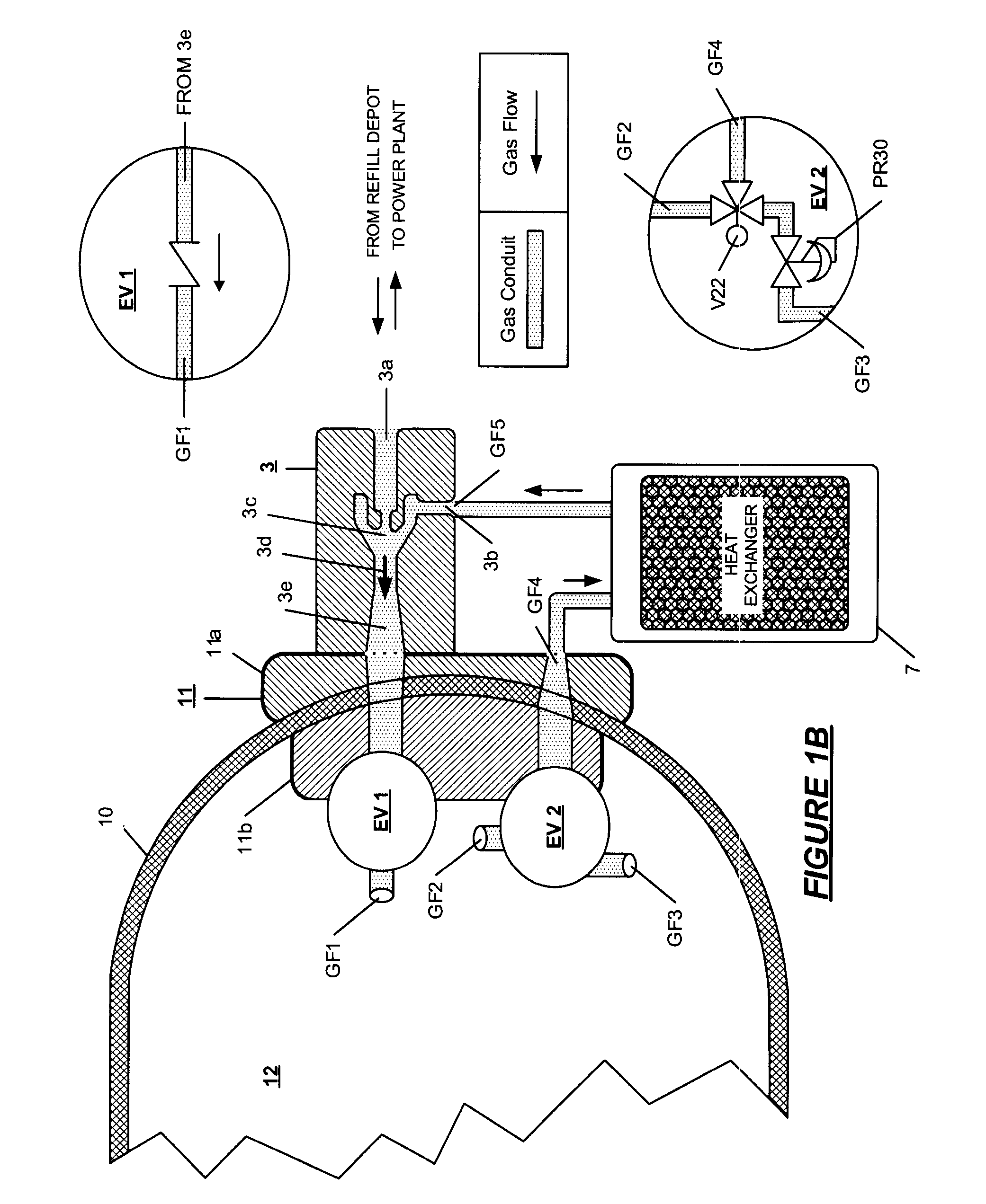
[0033]The various modes of vehicle operation are illustrated in the examples of FIG. 4A [refueling], FIG. 4B [driving] and FIG. 4C [parking]. In the refueling mode shown in FIG. 4A, tank boss or end cap port assembly 20 is provided at one end of the tank and includes embedded valve EV21, a one way check valve controlling gas flow GF1 into the tank from ejector pump 3. Boss or port assembly on the opposite end of the tank 21 includes, embedded therein, two switch valves, V2 and V3, and pressure regulator PR2. The switch valves and pressure regulator PR2 are interconnected in the gas flow conduit GF4 leading to the vehicle power plant through switched outlets from the tank GF2 and GF3. V2 and V3 may be combined into a single two way switch having the equivalent function. In the refuel mode, V1, leading to the power plant, is closed and the entry of gas from the nozzle 1 into the conduit 100 is allowed. Of the gas flow tubes associated with embedded valves and regulato...


PUM

PropertyMeasurementUnit
pressuresaaaaaaaaaa
pressuresaaaaaaaaaa
pressuresaaaaaaaaaa

Abstract

Apparatus for heat exchange in a high pressure gas storage tank wherein a heat absorbent gas media circulates within the tank and absorbs or radiates the heat resulting from compression and expansion of gas stored in the on board tank depending upon the mode of operation of the vehicle, the gas media is circulated through a heat exchange unit external to the tank whereby heat is radiated to or absorbed from an environment external to the tank, and an in situ heat exchange device installed within the tank absorbs or radiates the heat from or to the gas stored in the tank as a result of heat exchange through a unit external to the tank.

Description

RELATED APPLICATIONS[0001]This application is a continuation in part of my applications for U.S. Letters Pat. Ser. No. 11 / 682,574 filed Mar. 6, 2007, now U.S. Pat. No. 7,735,528, which is a continuation in part of U.S. patent application Ser. No. 11 / 279,574, filed Apr. 13, 2006, now U.S. Pat. No. 7,377,294, U.S. patent application Ser. No. 11 / 380,429 filed Apr. 27, 2006, now U.S. Pat. No. 7,637,292, U.S. patent application Ser. No. 11 / 381, filed May 1, 2006, now U.S. Pat. No. 7,681,604, and U.S. patent application Ser. No. 11 / 380,996 filed May 1, 2006, now U.S. Pat. No. 7,757,726; and U.S. patent application Ser. No. 11 / 687,905 filed Mar. 19, 2007 now U.S. Pat. No. 7,891,386, which is a continuation in part of U.S. Pat. No. 7,735,528.FIELD OF THE INVENTION[0002]The present invention relates to a system for cooling and heating high pressure gas stored in fuel tanks, typically, hydrogen gas and compressed natural gas introduced into a vehicle tank. Onboard high pressure tank cooling i...

Claims


Application Information

Patent Timeline
Patent Type & Authority Patents(United States)
IPC IPC(8): B65B1/04
CPCF17C5/007F17C7/00F17C13/025F17C13/026F17C5/06Y02E60/321F17C2201/0104F17C2201/056F17C2203/0617F17C2203/0619F17C2205/0326F17C2205/0338F17C2205/0397F17C2221/012F17C2221/033F17C2223/0123F17C2223/036F17C2225/0123F17C2225/036F17C2227/0114F17C2227/0309F17C2227/0311F17C2227/0316F17C2227/0323F17C2227/0327F17C2227/0341F17C2227/0344F17C2227/0348F17C2227/0355F17C2227/0372F17C2227/0388F17C2250/032F17C2250/043F17C2250/0439F17C2250/0491F17C2250/0626F17C2250/0631F17C2260/021F17C2260/025F17C2270/0168Y02E60/32
Inventor HANDA, KIYOSHI
Owner HONDA MOTOR CO LTD
Why Eureka
Try Eureka