Station Side Cooling for Refueling Vehicle Storage Tanks with High Pressure Fuel

a technology for refueling vehicle storage tanks and gas cooling, which is applied in lighting and heating apparatus, liquid handling, packaging goods types, etc., can solve the problems of reducing the initial tank temperature, difficulty in refueling to optimum capacity, and not being able to obtain a full refill tank pressure, etc., to reduce the cost and complexity of cooling systems, reduce the effect of energy consumption and enhancing efficiency

Inactive Publication Date: 2008-12-11
HONDA MOTOR CO LTD
View PDF15 Cites 18 Cited by
  • Summary
  • Abstract
  • Description
  • Claims
  • Application Information

AI Technical Summary

Benefits of technology

[0005]It is an object of the present invention to minimize energy use and reduce the expense and complexity of cooling systems used to enhance efficiency in high pressure fuel gas refilling systems. Typically, each time a vehicle is refueled with high pressure gas, compression energy results in tank (namely, the gas inside the tank) heating, hence, it is an object of the invention to minimize high pressure gas and tank heating and to increase the efficiency and refueling capacity of an on board fuel storage tank in high pressure gas powered motor vehicles. It is an object of the invention to provide a station side cooling system that can remove the compression heat resulting from the refueling of an on board tank during a high pressure refuel. A faster refueling time, increased refueling efficiency and overall vehicle range increase will result because improved tank capacity per unit volume is achieved, particularly where nominal or optimum design capacity refill pressure approaches 10,000 psi (70 MPa) or greater.

Problems solved by technology

Conventionally, it is not usually possible to obtain a full refill tank pressure to a high pressure design maximum, for example, 10,000 psi (70 MPa), without a pressure or temperature compensation system during the course of refueling.
As higher tank design pressures are utilized, a full tank refill to optimum capacity becomes more difficult and an underfill results.
A slower flow rate during refill results in a lower initial tank temperature, however, a slow fill, is undesirable, and may be impractical when significant numbers of refuel customers are involved.
An undesirable consequence of a slower flow rate during refueling to avoid heat build up is a longer refueling time.
Pre-cooling to a very low temperature to ameliorate compression heating effects, however, requires substantial energy, thereby reducing the overall energy efficiency of a high pressure gas infrastructure.
Higher pressure, however, exacerbates the heat generated in the tank as a result of higher pressure compression.

Method used


Image

  • Station Side Cooling for Refueling Vehicle Storage Tanks with High Pressure Fuel
  • Station Side Cooling for Refueling Vehicle Storage Tanks with High Pressure Fuel
  • Station Side Cooling for Refueling Vehicle Storage Tanks with High Pressure Fuel

Examples


Embodiment Construction

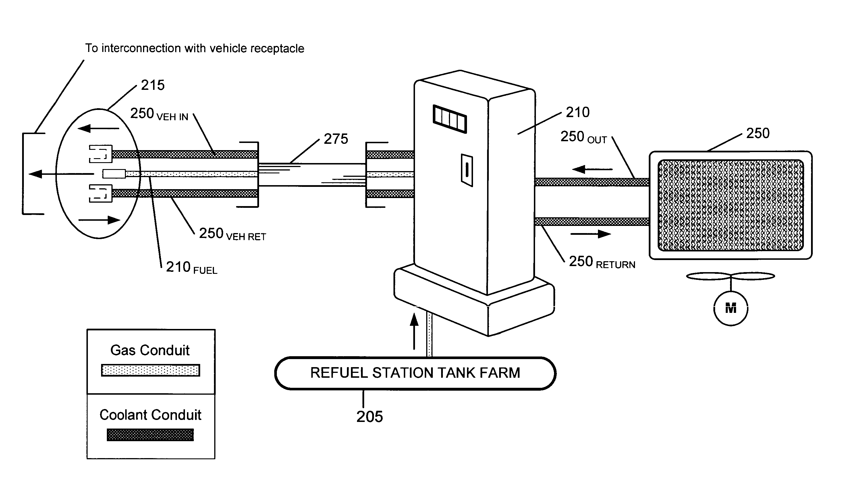
[0014]The invention increases the refueling energy efficiency of hydrogen powered vehicles by withdrawing the heat of refilling compression from the high pressure gas introduced into on board tanks whether or not a slow fill, a pressure overfill or pre cooling of the gas occurs at the refueling station. Because the invention reduces the overall energy required to recharge the on board vehicle tanks with high pressure gas to a full optimal state, overall infrastructure energy requirements are reduced. When a full refill is achieved, vehicle mileage range is increased, the need for short interval refills is reduced, and consumer satisfaction is enhanced. A cooling circuit is disposed within the on board tank circulating the refill gas through an in situ on board tank HEX 1. Heat absorbed in HEX 1 is conveyed by the circulating refueling gas to a second heat exchanger, HEX 2, exterior to the tank, where the absorbed heat is eliminated by an ambient temperature heat exchange.

[0015]The i...


PUM

PropertyMeasurementUnit
ambient temperatureaaaaaaaaaa
pressureaaaaaaaaaa

Abstract

Reduction of fuel tank heating during the refueling process is effected by a coolant exchange between the station and the vehicle whereby an on board heat exchanger internal to the tank is interconnected through a heat exchanger external to the tank with a station side cooler that cools the refill gas to an ambient temperature. As a result of station provided ambient temperature cooling, the vehicle does not need to have particularly complicated on-board cooling devices, nor does the station need to be encumbered with complex and expensive pre cooling devices.

Description

FIELD OF THE INVENTION[0001]The present invention relates to a station side gas cooling apparatus and a system for enhancing the refueling efficiency of on board vehicle high pressure storage tanks for compressed natural gas or hydrogen.BACKGROUND OF THE INVENTION[0002]When hydrogen is used as a fuel in motor vehicles, a hydrogen fuel depot infrastructure for refueling must also be developed. Typically, in the use of hydrogen to fuel motor vehicles, or in the use of compressed natural gas (CNG) to power engines in motor vehicles, present practice is that hydrogen is stored in refillable on board fuel tanks having a maximum design pressure in the range of about 5000 psi, CNG is stored in tanks having a maximum design pressure in the range of about 3600 psi. Pressures exceeding 3600 psi for CNG and 5000 psi for hydrogen and in the range of about 10,000 psi or more are likely to be utilized as the use of high pressure fuel gas technology becomes more widespread in motor vehicle applica...

Claims


Application Information

Patent Timeline
Patent Type & Authority Applications(United States)
IPC IPC(8): F24H3/00
CPCF17C5/007F17C5/06F17C2221/012F17C2221/033F17C2223/0123F17C2223/036F17C2225/0123F17C2225/036F17C2227/0341F17C2227/0344F17C2227/0372F17C2260/025F17C2270/0139F17C2270/0178Y02E60/321Y02E60/32
Inventor HANDA, KIYOSHI
Owner HONDA MOTOR CO LTD
Why Eureka
Try Eureka