Gas Cooling Method Using a Melting/Solidifying Media for High Pressure Storage Tanks for Compressed Natural Gas or Hydrogen

a technology of compressed natural gas and gas cooling, which is applied in the direction of electrochemical generators, container discharging methods, packaged goods types, etc., can solve the problems of reducing the overall energy efficiency of hydrogen economy, not being able to obtain a full refilling tank pressure, and reducing the initial tank temperature. , to achieve the effect of reducing energy costs, improving high pressure gas refilling systems, and reducing energy consumption

Inactive Publication Date: 2007-01-04
HONDA MOTOR CO LTD
View PDF3 Cites 17 Cited by
  • Summary
  • Abstract
  • Description
  • Claims
  • Application Information

AI Technical Summary

Benefits of technology

[0006] It is an object of the present invention to enhance refueling efficiency, to minimize energy expense and to improve high pressure gas refilling systems such that, when factored into the overall infrastructure of hydrogen powered vehicles and fuel depots, added energy efficiency results. Typically, each time a vehicle is refueled with hydrogen, compression energy results in tank heating, hence, it is an object of the invention to provide an on board vehicle system and apparatus to minimize tank heating at the refueling depot and to increase the efficiency and refueling capacity of an on board high pressure fuel storage tank in a gas powered motor vehicle.
[0007] The invention provides a system that can remove the compression heat resulting from refueling an on board tank during refueling. A significantly faster refueling time, increased refueling efficiency and overall vehicle range will increase as a result of improved tank capacity per unit volume, particularly where nominal refill pressure is above 3600 psi and 5000 psi and reaches the range of 10,000 psi or greater. In accordance with the present invention, effective solutions to fuel tank heating during the refueling process include a system for heat evacuation in which a tank in

Problems solved by technology

Conventionally, it is not usually possible to obtain a full refill tank pressure to a high pressure design maximum without some form of secondary gas processing.
A third variation of an attempt to resolve the less than full fill problem involves a slow flow rate during refill resulting in a lower initial tank temperature, however, a slow

Method used


Image

  • Gas Cooling Method Using a Melting/Solidifying Media for High Pressure Storage Tanks for Compressed Natural Gas or Hydrogen
  • Gas Cooling Method Using a Melting/Solidifying Media for High Pressure Storage Tanks for Compressed Natural Gas or Hydrogen
  • Gas Cooling Method Using a Melting/Solidifying Media for High Pressure Storage Tanks for Compressed Natural Gas or Hydrogen

Examples


Embodiment Construction

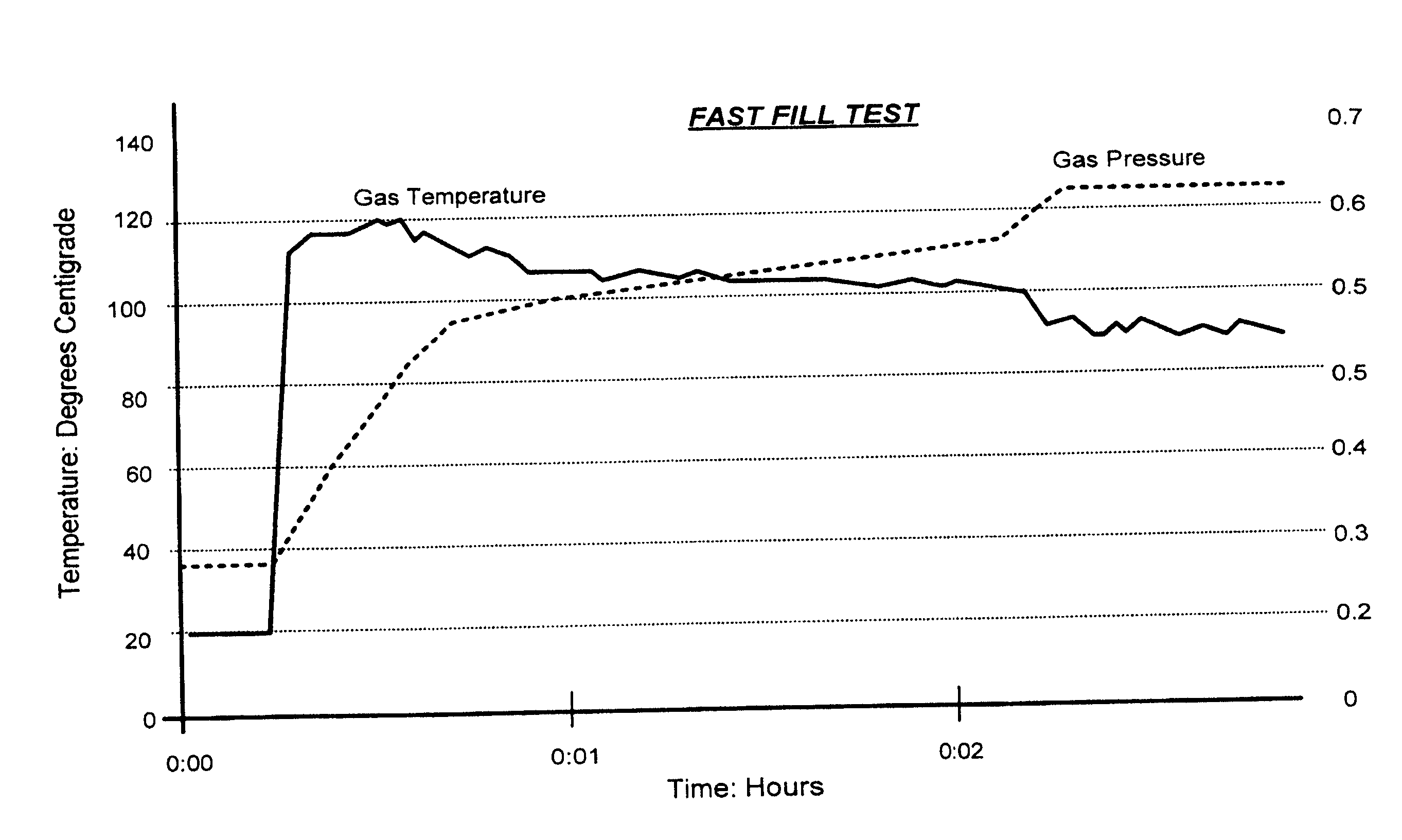
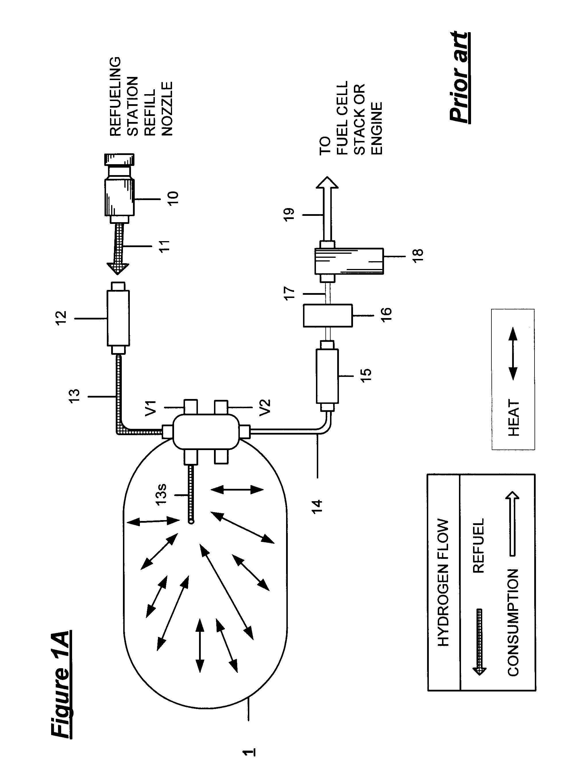
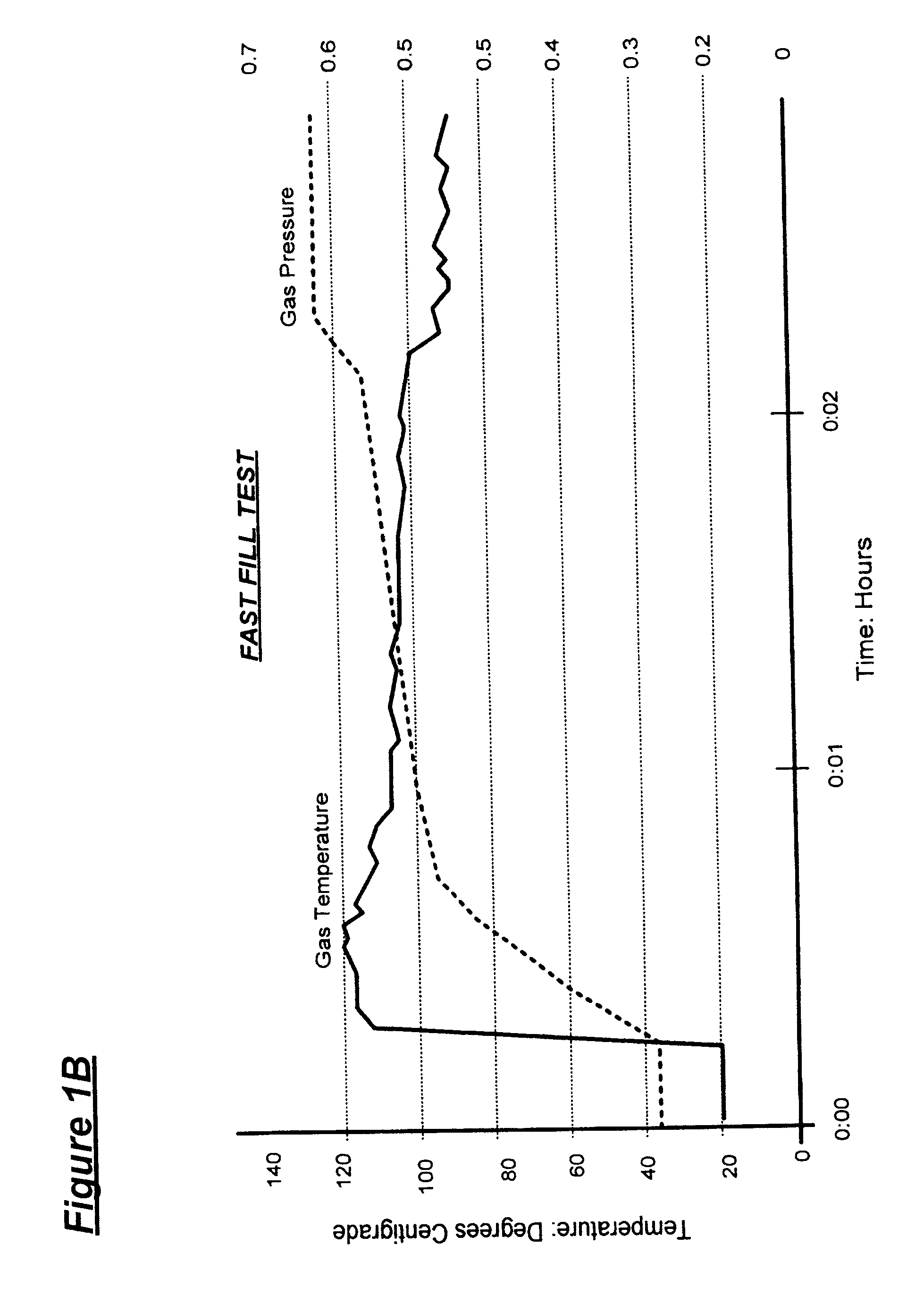
[0014] In brief, a system is provided for a gas powered vehicle having an on board tank for the storage of a fuel gas under high pressure. The tank refill capacity is enhanced and the time required to refill one or more than one on board fuel tank is reduced. A melting / solidifying heat absorbent media within the tank absorbs heat of compression resulting from the refueling process, and the absorbed heat may be conducted to a radiator external to the tank to exhaust the absorbed heat from the tank to an external environment.

[0015] The system of the invention increases the refueling energy efficiency of high pressure gas powered vehicles by withdrawing the heat of refilling compression from the on board tanks and by eliminating the need for a pressure overfill and / or refueling station pre-cooling of the gas before a tank refill. Less compression energy is required to refill the tanks; the invention increases the total energy efficiency of CNG or hydrogen station high pressure gas uti...


PUM

PropertyMeasurementUnit
Temperatureaaaaaaaaaa
Pressureaaaaaaaaaa
Melting pointaaaaaaaaaa

Abstract

A system for increasing the overall efficiency of a high pressure gas fueled vehicle and refilling station infrastructure wherein the compression heat of high pressure refueling of an on board tank is absorbed by a temperature dependent melting/solidifying media within the interior of an on board tank and may be dispersed through an external radiator.

Description

RELATED APPLICATIONS [0001] This application is related to and claims all benefits under 35 U.S.C. § 119(e) of my earlier U.S. Provisional Patent Application Ser. No. 60 / 679,102 filed on May 9, 2005, entitled “Gas Cooling Method Using a Melting / Solidifying Media for High Pressure Storage Tanks for Compressed Natural Gas or Hydrogen.”FIELD OF THE INVENTION [0002] The present invention relates to a gas cooling method using a melting / solidifying media for high pressure storage tanks for compressed natural gas or hydrogen. Particularly, the invention provides an on board system and apparatus for efficiently refueling the on board vehicle gas tanks with hydrogen and / or compressed natural gas (CNG) when the vehicle is refueled at high pressure from high pressure storage tanks used at refueling stations or depots. BACKGROUND OF THE INVENTION [0003] When hydrogen is used as a fuel in motor vehicles, a hydrogen fuel depot infrastructure for refueling must also be developed. Typically, in the...

Claims


Application Information

Patent Timeline
IPC IPC(8): B65B1/28
CPCF17C5/007F17C2270/0184Y02E60/321F17C5/06F17C2201/0109F17C2201/056F17C2201/058F17C2203/0619F17C2203/0663F17C2205/0323F17C2221/012F17C2221/033F17C2223/0123F17C2223/036F17C2227/0365F17C2227/0397F17C2227/04F17C2260/023F17C2260/025F17C2265/065F17C2270/0165F17C2270/0178F17C13/001Y02E60/32
Inventor HANDA, KIYOSHI
Owner HONDA MOTOR CO LTD
Why Eureka
Try Eureka