Thermal Management For High Pressure Storage Tanks

a technology of high-pressure storage tanks and thermal management, which is applied in the direction of lighting and heating apparatus, packaging goods types, and container discharge methods, etc., can solve the problems of reducing the efficiency of internal heat exchangers to less than 100%, and achieve the effect of reducing the cost and weight of gas cooling equipment on board, improving cooling capacity, and reducing the cost and weight of gas cooling equipmen

Inactive Publication Date: 2008-12-11
HONDA MOTOR CO LTD
View PDF2 Cites 15 Cited by
  • Summary
  • Abstract
  • Description
  • Claims
  • Application Information

AI Technical Summary

Benefits of technology

[0009]The system described herein provides onboard cooling; as a result, there is no need to change the refueling station equipment. The cost and weight of on board gas cooling equipment, important factors in the adoption of high pressure fueled vehicles, are reduced. Cooling capacity is improved; continuous cooling is provided. Heat exchange efficiency approaches 100%. When there is an internal heat exchanger, the gas temperature in the heat exchanger is not perfectly equal to tank gas temperature, thus reducing internal heat exchanger efficiency to less than 100%. In the gas ejector system described herein, the gas flow cooling circuit, through an in situ device or a Venturi pump is interconnected with an external heat radiator or a vehicle sub cooling system such as an air conditioner, thereby collecting interior tank heat and radiating the absorbed heat into the ambient atmosphere or other system appropriate for the use, radiation, absorption, or disposal of the collected heat of high pressure refueling. Utilized in reverse, the cooling devices will heat the tank gas while the vehicle is being operated and increase gas utilization in a refill.

Problems solved by technology

When there is an internal heat exchanger, the gas temperature in the heat exchanger is not perfectly equal to tank gas temperature, thus reducing internal heat exchanger efficiency to less than 100%.

Method used


Image

  • Thermal Management For High Pressure Storage Tanks
  • Thermal Management For High Pressure Storage Tanks
  • Thermal Management For High Pressure Storage Tanks

Examples


Embodiment Construction

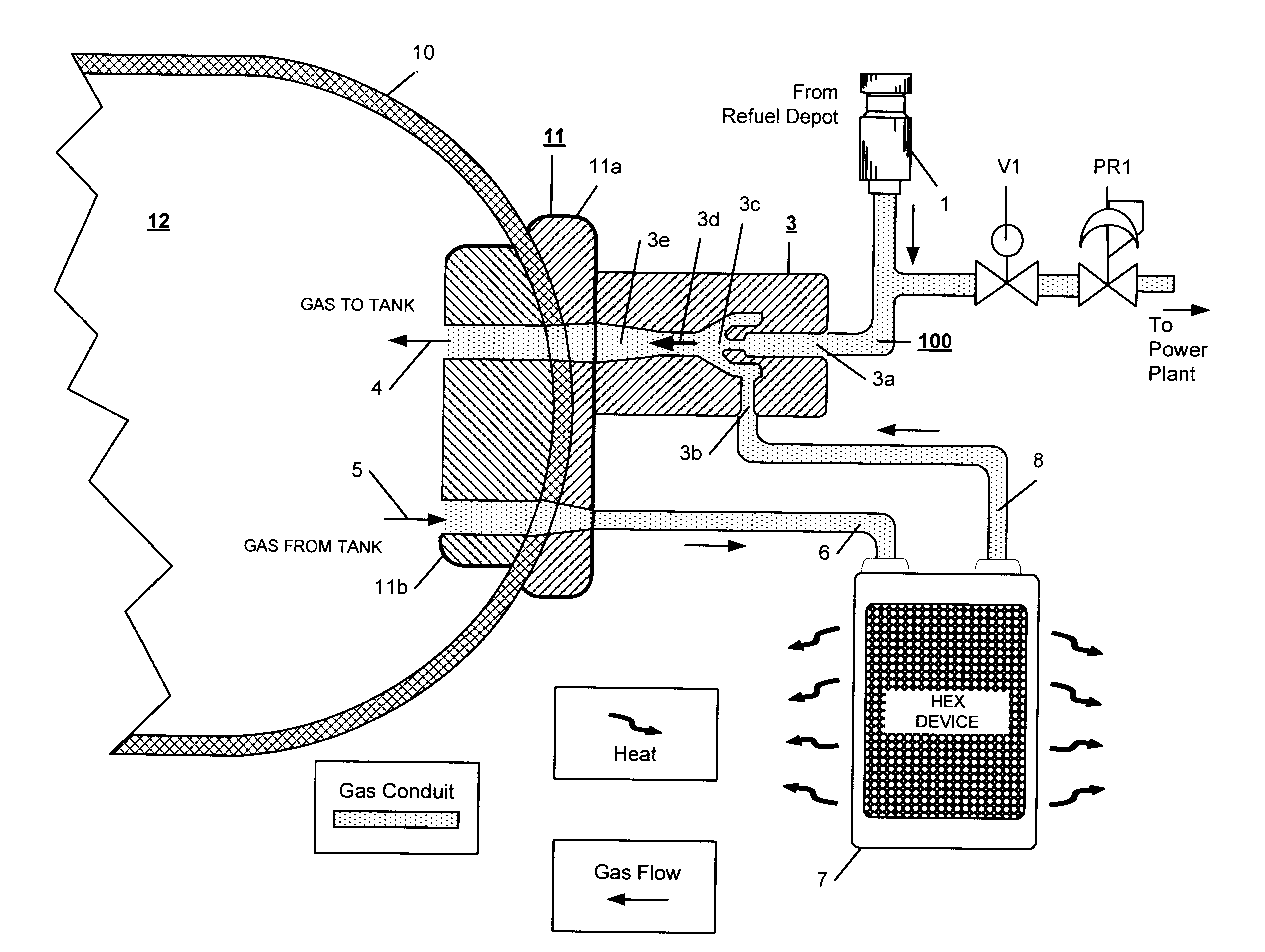
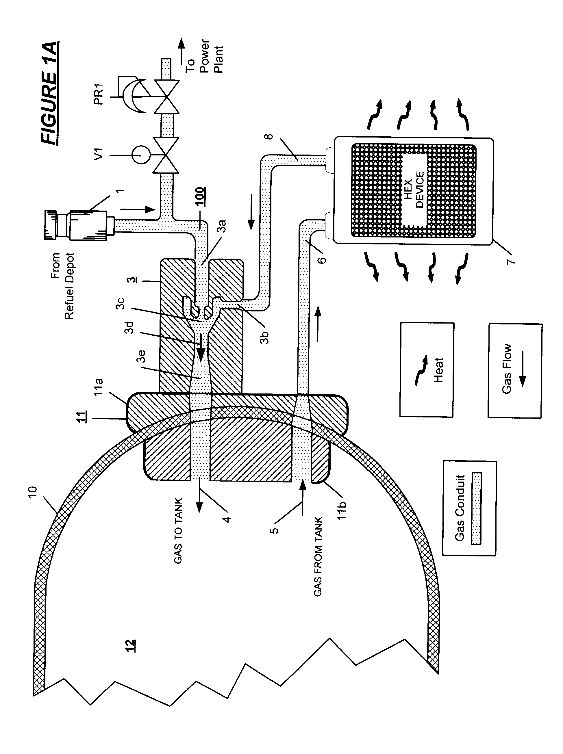
[0029]The system of the invention increases the refueling energy efficiency of high pressure gas powered (Hydrogen and CNG) vehicles by withdrawing the heat of compression resulting from tank refilling from the high pressure gas introduced into on board tanks and by eliminating the need for a slow fill, a pressure overfill and / or refueling station precooling of the gas. Overall, high pressure gas infrastructure energy requirements for motor vehicles are reduced, vehicle mileage range is increased when tank capacity is expanded, the need for short interval refills is eliminated, vehicle weight and cost are reduced, and consumer satisfaction is enhanced.

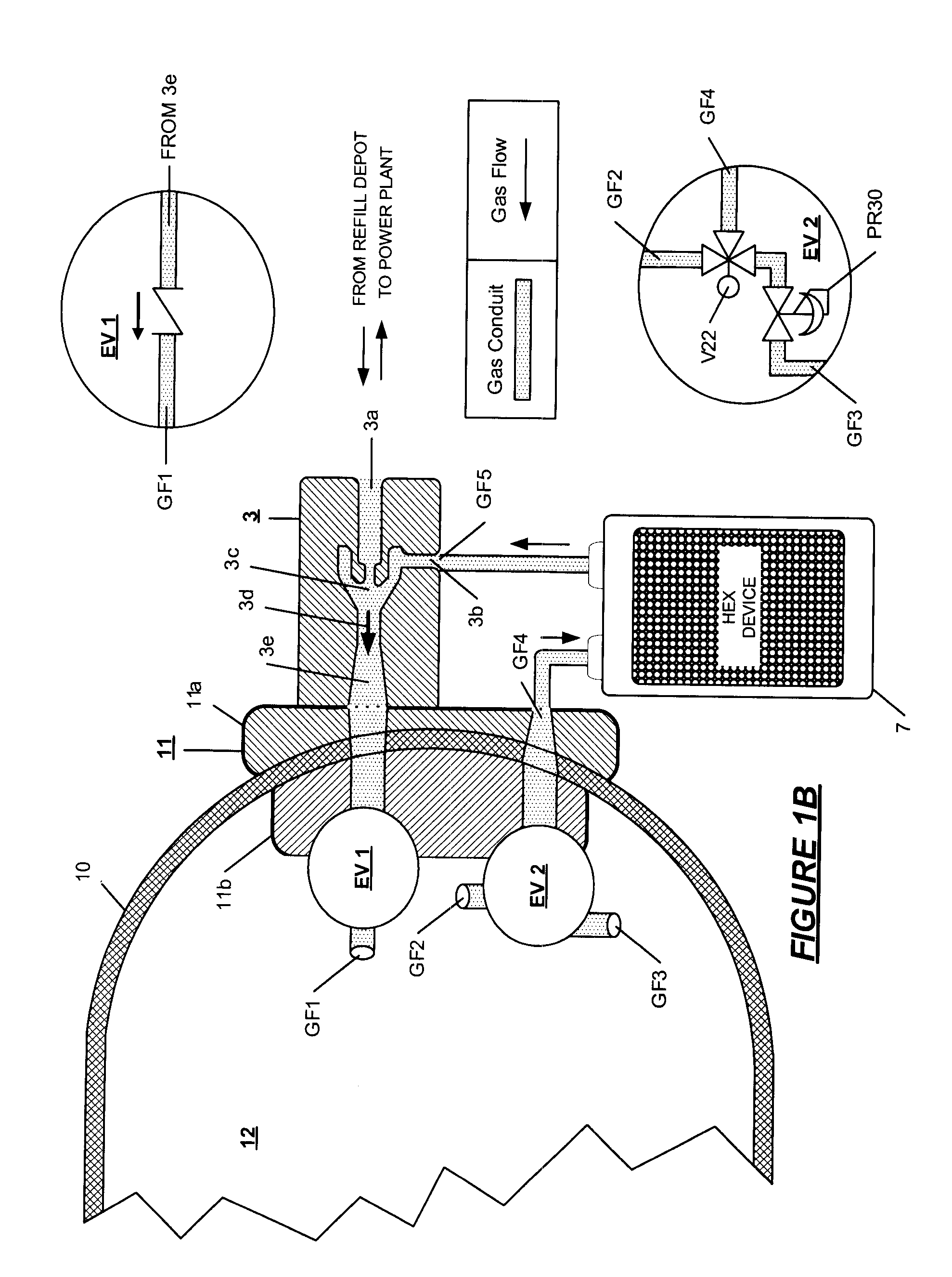
[0030]With reference to FIG. 1A an example of a cooling system using an ejector pump fixed at one end cap or port assembly 11 comprised of mating elements 11a and 11b of a fuel storage tank 10 having interior gas storage volume 12 is shown. An ejector pump 3 is installed at the cap assembly providing a gas flow circuit 100 within the s...


PUM

PropertyMeasurementUnit
pressuresaaaaaaaaaa
pressuresaaaaaaaaaa
pressuresaaaaaaaaaa

Abstract

Apparatus for the thermal management of high pressure gas storage tanks wherein the compression heat of refueling the tank is evacuated from the interior of the tank in which a gas circulates within the tank powered by a pump powered and as the gas traverses from the high pressure refuel depot to the storage tank, the circulating gas absorbs the refueling heat and carries the heat to a cooling system having a supplemental heat exchange device before the gas is introduced into the tank. The apparatus may be operated in reverse to transfer heat from a source to the tank interior to provide more complete exhaustion of the tank during vehicle operation.

Description

RELATED APPLICATIONS[0001]This application is a continuation in part of my co-pending application for United States Letters Patent High Pressure Gas Tank Cooling by Ejector Pump Circulation, Ser. No. 11 / 682,574 filed on Mar. 6, 2007.FIELD OF THE INVENTION[0002]The present invention relates to a system for cooling high pressure gas stored in fuel tanks, typically, hydrogen gas and compressed natural gas introduced to the tank at a refueling station. Onboard high pressure tank cooling is effected by direct gas ejecting using a Venturi pump or another mechanical pump to circulate refill gas to absorb heat within and to transfer absorbed heat to an environment external to the tank.BACKGROUND OF THE INVENTION[0003]In motor vehicles using hydrogen or using compressed natural gas (CNG) to power vehicle engines, present practice is that fuel is stored in on board tanks maintained at a maximum pressure in the range of about 5000 psi for hydrogen and 3600 psi for CNG. Higher pressures in the ...

Claims


Application Information

Patent Timeline
Patent Type & Authority Applications(United States)
IPC IPC(8): F17C7/02F25B19/00F17C9/02
CPCF17C5/007Y02E60/321F17C7/00F17C2205/0397F17C2221/012F17C2221/033F17C2223/0123F17C2223/036F17C2225/0123F17C2225/036F17C2227/0355F17C2227/0372F17C2260/021F17C2260/023F17C2270/0168F17C5/06Y02E60/32
Inventor HANDA, KIYOSHI
Owner HONDA MOTOR CO LTD
Why Eureka
Try Eureka