Automatic attaching machine for electronic product auxiliary materials

A technology for electronic products and laminating machines, which is applied in the direction of material gluing, telephone structure, mechanical equipment, etc.

Pending Publication Date: 2019-02-15
SHENZHEN NUOFENG OPTOELECTRONICS EQUIP
View PDF0 Cites 10 Cited by
  • Summary
  • Abstract
  • Description
  • Claims
  • Application Information

AI Technical Summary

Problems solved by technology

The traditional manual assembly method can no longer meet the production capacity and quality requirements of this kind of multi-part assembly. An automatic production line needs to be designed for this kind of glass sheet assembly process. Full automation from film to finished product blanking
In the design process of the automatic assembly line for this kind of glass sheet assembled finished product, there are the following technical difficulties: 1. It is necessary to design a jig according to each assembly station of the automated assembly line, and the jig needs to be set for each accessory of the product Bearing plane, so as to play a load-bearing role in the assembly process of accessories, and cooperate with the positioning and supporting mechanism to complete the positioning of the fixture at the assembly station, and the role of the positioning and supporting mechanism for absorbing / lifting the product; 2. It is necessary to design a A positioning and support mechanism that can be commonly used in each station of the accessory assembly automation production line to position the fixture, and can assist the fixture to lift upward to support the product or absorb and heat the product during the assembly process; 3. It needs to be based on the automated assembly production The materials required by each assembly station of the line (such as back glue, foam and other materials are generally adhered to the material belt when they come in, and are wound by the material belt, so that a large amount of material can be supplied in a concentrated manner). Design a supply system The feeding device, through which the feeding of various materials can be realized, that is, it is necessary to be able to assemble multiple coils at the same station at the same time; at the same time, considering the versatility of the automatic assembly line mechanism, the feeding mechanism is required to be convenient It can be disassembled quickly so that it can be assembled to different workstations according to actual production requirements; 4. The traditional roll feeding mechanism generally drives the roll to rotate through the winding motor to pull the material belt out from the roll, and the winding The tension between the roll and the material roll is tensioned by the tension wheel; however, in the actual discharge process, the material belt is often stuck when the rewinding motor rotates and rewinds, which may easily cause the material belt to be broken and affect the material supply. The feeding device is required to have auxiliary feeding parts to reduce the jamming of the discharging material and the breaking of the material belt, so as to ensure the continuous and normal operation of the feeding material; A robot that is taken out from the feeding mechanism and transported to the working station, where the auxiliary materials or accessories are attached or assembled to form product components; at the same time, in order to ensure the replaceability of the structural components of each station in the whole line, it is required that the The manipulator has strong versatility; in addition, in order to improve the efficiency of the manipulator for picking or laminating, it is necessary for the manipulator to have the function of taking out or placing multiple auxiliary materials or accessories at the same time

Method used


Image

  • Automatic attaching machine for electronic product auxiliary materials
  • Automatic attaching machine for electronic product auxiliary materials
  • Automatic attaching machine for electronic product auxiliary materials

Examples


Embodiment Construction

[0055] The present invention will be further described below in conjunction with accompanying drawing:

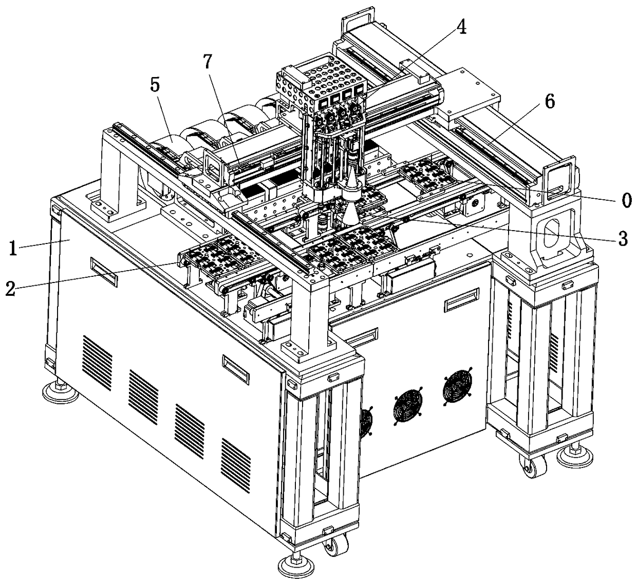
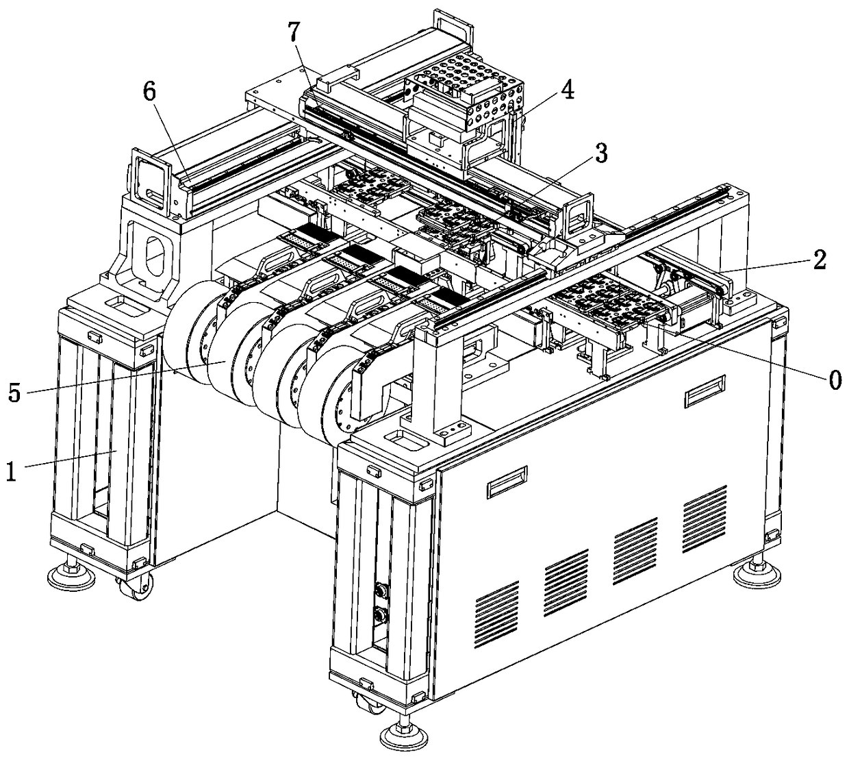
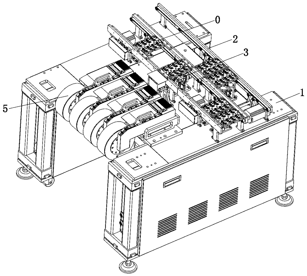
[0056] Such as Figure 1 to Figure 4 As shown, the technical solution adopted by the present invention is as follows: an automatic laminating machine for auxiliary materials of electronic products, including a transmission mechanism 2, a positioning and support mechanism 3, a placement mechanism 4 and a feeding mechanism 5, wherein the above-mentioned transmission mechanism 2 is horizontally arranged On the frame 1, the two ends of the transmission mechanism 2 are docked with the transmission belt of the automatic assembly line for electronic product accessories, and the jig 0 loaded with the product is placed on the timing belt inside the two brackets set in parallel with the transmission mechanism 2 and passed through the timing belt. Transmission and linear motion; the above-mentioned positioning and supporting mechanism 3 is set at the laminating station in the transmis...


PUM


Abstract

The invention discloses an automatic attaching machine for electronic product auxiliary materials. The automatic attaching machine comprises a conveying mechanism, a positioning and supporting mechanism, an attaching mechanism and a material supplying mechanism; the conveying mechanism is horizontally arranged on a rack; the positioning and supporting mechanism is arranged at an attaching stationin the conveying mechanism, when a fixture moves to the attaching station, the fixture is positioned by the positioning and supporting mechanism, and a product in the fixture penetrates through the fixture upwards to be jacked and supported and adsorbed and fixed downwards through the positioning and supporting mechanism; the material supplying mechanism is arranged on one side of the conveying mechanism and used for guiding out at least two auxiliary materials; and the attaching mechanism is arranged between the attaching station and the material supplying mechanism in a crossing mode and used for attaching the auxiliary materials to the product after the auxiliary materials guided out of the material supplying mechanism are adsorbed, fixed and moved to the attaching station. According tothe automatic attaching machine for the electronic product auxiliary materials, the functions of multi-product bearing, fixture positioning, product jacking and supporting and adsorbing and heating are achieved, the material supplying assembly achieves quick disassembling and replacing, the condition that a material belt is jammed and pulled to be broken is reduced, a multi-material automatic material taking and attaching function is achieved, the universality is high, and the part replaceability is high.

Description

technical field [0001] The invention relates to the field of automatic manufacturing, in particular to an automatic bonding machine for auxiliary materials of electronic products. Background technique [0002] Smartphones are smart terminal devices that have developed rapidly in recent years. With the development of mobile phone technology, they have integrated a variety of electronic product functions, and have gradually become an indispensable tool in people's daily production and life; the development of smart phones has also driven its downstream The development of industries such as accessories and their assembly; current smartphones generally integrate shooting functions, and the camera of the mobile phone is installed on the front and rear sides of the phone; in the actual manufacturing process, a layer of glass needs to be assembled on the outside of the camera to achieve protection. The camera and the purpose of increasing the light effect of the camera; the finishe...

Claims


Application Information

Patent Timeline
Patent Type & Authority Applications(China)
IPC IPC(8): F16B11/00H04M1/02
CPCF16B11/002F16B11/006H04M1/02
Inventor 许立峰贺谦余红杰曹锦
Owner SHENZHEN NUOFENG OPTOELECTRONICS EQUIP
Why Eureka
Try Eureka