Horizontal-array high-power semiconductor laser capable of replacing chip

A laser and high-power technology, applied in the direction of semiconductor lasers, semiconductor laser devices, lasers, etc., can solve the problems of laser output wavelength drift, long heat dissipation path, poor heat dissipation, etc., and achieve strong output wavelength selectivity and high power Requirements, improve the effect of wavelength consistency

Active Publication Date: 2010-09-22
FOCUSLIGHT TECH
View PDF7 Cites 9 Cited by
  • Summary
  • Abstract
  • Description
  • Claims
  • Application Information

AI Technical Summary

Problems solved by technology

[0004] 1) Poor heat dissipation: For conduction-cooled high-power semiconductor laser arrays (E.Deichsel; D. J.Meusel, etc., High Reliable qcw Laser Bars andStacks, Proceedings of SPIE, 2008.6876 (68760K)), the light emitted by the laser is vertically upward
The distance between multiple bars is very short, and more heat will be generated when working in high repetition frequency mode. The heat is only exported by the metal heat sinks on both sides, and the heat dissipation path is relatively long, which can easily lead to ineffective The heat concentration in the source area makes the heat of the laser uneven, which eventually leads to wavelength drift of the laser, broadening of the spectrum, performance stability degradation, poor reliability, and shortened service life
Moreover, it is very difficult to make the light-emitting surface at the same horizontal position in the horizontal direction for multiple bars.
[0005] 2) Poor replaceability: For conduction cooling high-power semiconductor laser arrays and liquid-cooled horizontal array high-power semiconductor laser arrays (a high-power semiconductor laser, Chinese invention patent, publication number CN101071933, publication date November 14, 2007) , because the horizontal array structure is welded together by multiple bars, once a bar is burned, short-circuited or not working properly, it will directly affect the output power and output beam of the entire laser, so it cannot be replaced
At the same time, the undamaged bars in the array will be wasted, so the manufacturing cost is very high
[0006] 3) It is impossible to individually age each chip: Since the existing horizontal array products are made by direct reflow molding of multiple bars, each chip cannot be individually aged before assembly, and the entire chip can only be aged after assembly. Device aging
In this way, if one or several bars are burnt, short-circuited or not working properly, the entire device will also fail.
[0007] 4) The number of chips is limited: Since the existing patented products are made by reflow molding multiple bars at one time, the number of chips should not be too large during production, otherwise it will be difficult to ensure the installation accuracy and the consistency of light emission, so the number of chips Usually controlled within 3-4, which limits the power expansion of horizontal array semiconductor lasers
[0008] 5) High cost: Since the existing horizontal array products are made by reflow molding of multiple bars at one time, if one or more bars are burned, short-circuited or not working properly during the overall aging process, the entire device will not work
Lasers are therefore expensive to manufacture
[0009] 6) Short service life: During the working process of the laser, the heat dissipation effect of the existing horizontal array products is not high, which easily causes serious heat concentration of the laser, resulting in drift of the output wavelength of the laser, broadening of the spectrum, and decline in performance stability , resulting in short reliability and lifetime of the laser

Method used


Image

  • Horizontal-array high-power semiconductor laser capable of replacing chip
  • Horizontal-array high-power semiconductor laser capable of replacing chip
  • Horizontal-array high-power semiconductor laser capable of replacing chip

Examples


Embodiment Construction

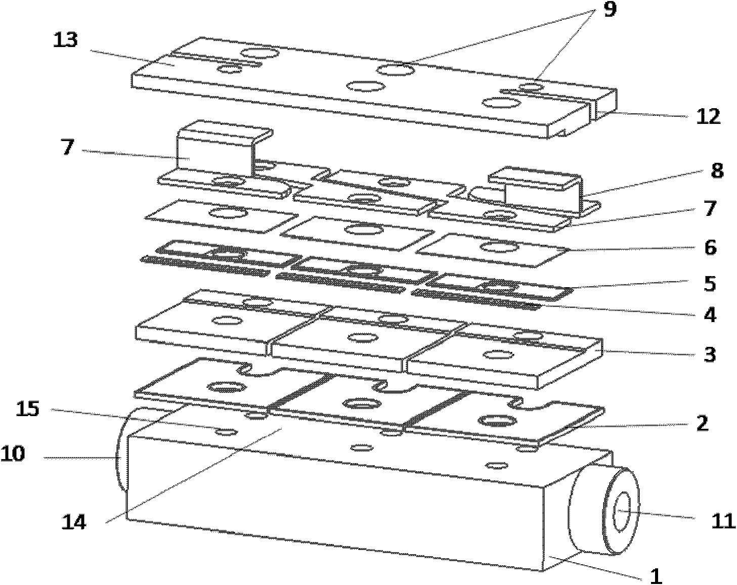
[0029] The present invention is described in further detail below in conjunction with accompanying drawing:

[0030] see figure 1 , the replaceable chip horizontal array high-power semiconductor laser of the present invention includes a refrigerator 1 made of a bar-shaped block, and the interior of the refrigerator 1 is provided with one or more parallel liquid channels in the axial direction, and the liquid channels are in the Both ends of the refrigerator 1 are provided with a refrigerator water inlet 11 and a refrigerator water outlet 10 respectively, and the cross-sectional shape of the liquid channel is rectangular, circular or elliptical. When multiple liquid passages are provided inside the refrigerator 1 , the multiple liquid passages may also share a set of water inlets and outlets, or multiple sets of water inlets and outlets may be provided at both ends of the refrigerator 1 . In order to improve the heat dissipation effect, the refrigerator 1 is made of materials ...


PUM


Abstract

The invention discloses a horizontal-array high-power semiconductor laser capable of replacing a chip, which comprises a refrigerator. A liquid passage is arranged in the refrigerator; the upper end face of the refrigerator is a horizontal mounting surface; a plurality of laser chip mounting components, which are parallel to and independent from one another, are arranged on the horizontal mounting surface; each laser chip mounting component consists of the chip, and a lower insulating strip, a positive heat sink, an upper insulating strip, a chip cathode connection piece and an electrode connection piece which are sequentially laminated and fixed from bottom to top; the anode surfaces of the chips are connected with the positive heat sinks, while cathode surfaces are connected with the electrode connection pieces; and fixed plates are arranged at the upper ends of the plurality of laser chip mounting components. In the horizontal-array high-power semiconductor laser capable of replacing the chip, the plurality of independent laser chips (bars) are taken as cores and are arranged into a laser chip mounting component array in a horizontal direction, and the plurality of laser chip mounting components share the refrigerator, so thermal resistance can be reduced, radiation capacity can be improved, the optical output power of the laser is improved, and the quality of laser beams can be greatly improved under the condition of adding an alignment system.

Description

technical field [0001] The invention belongs to the field of laser manufacturing, and relates to a semiconductor laser, in particular to a replaceable chip horizontal array high-power semiconductor laser. Background technique [0002] With the continuous improvement of the output power, conversion efficiency and performance stability of semiconductor lasers, high-power semiconductor lasers are more widely used in industry, medical treatment and military affairs, the market demand is huge, and the development prospects are broader. At present, the main problems faced by high-power semiconductor lasers are still the output optical power, conversion efficiency, reliability, poor performance stability and high cost of the laser, which seriously restrict its application space. The performance of the laser is not only related to the chip, but also related to the heat dissipation and packaging of the laser. In order to improve the reliability and performance stability of the laser...

Claims


Application Information

Patent Timeline
IPC IPC(8): H01S5/024H01S5/40
Inventor 刘兴胜张艳春张路宗恒军杨培彬袁振邦梁雪杰李锋
Owner FOCUSLIGHT TECH
Why Eureka
Try Eureka