Propulsion system with integrated pylon

a propulsion system and integrated technology, applied in the direction of efficient propulsion technologies, machine supports, machines/engines, etc., can solve the problems of over-all flexing in the engine case line, and achieve the effect of simple, effective and economical

Active Publication Date: 2011-05-10
SN DETUDE & DE CONSTR DE MOTEURS DAVIATION S N E C M A
View PDF10 Cites 12 Cited by
  • Summary
  • Abstract
  • Description
  • Claims
  • Application Information

AI Technical Summary

Benefits of technology

[0004]A subject of the present invention is a propulsion system of the type described hereinabove which avoids the aforementioned disadvantages of the prior art in a way that is simple, effective and economical.
[0006]This downstream cylindrical part of the nacelle, termed the “OFS” (Outer Fixed Structure) in the art, has a rigidity which allows it to transmit loads between the engine and the airplane. Attaching it to the intermediate case of the engine allows it to support the engine in full and makes it possible to eliminate the suspensions and, in part, the pylon used in the prior art, which is replaced by far lighter weight means for securing to the airplane, resulting in a considerable weight saving. This attachment also makes it possible to eliminate the local load being points that were to be found in the prior art and allows the loads transmitted to be spread over a wider area, extending over at least 180° about the axis at the external periphery of the intermediate case and preferably over 360° and therefore over the entire external periphery of the intermediate case.

Problems solved by technology

The fact that the engine is attached using a pylon and suspensions also means that the thrust is reacted along a line that is offset from the axis of the engine, leading to overall flexing in the engine case line.

Method used


Image

  • Propulsion system with integrated pylon
  • Propulsion system with integrated pylon
  • Propulsion system with integrated pylon

Examples


Embodiment Construction

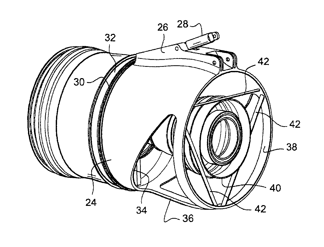
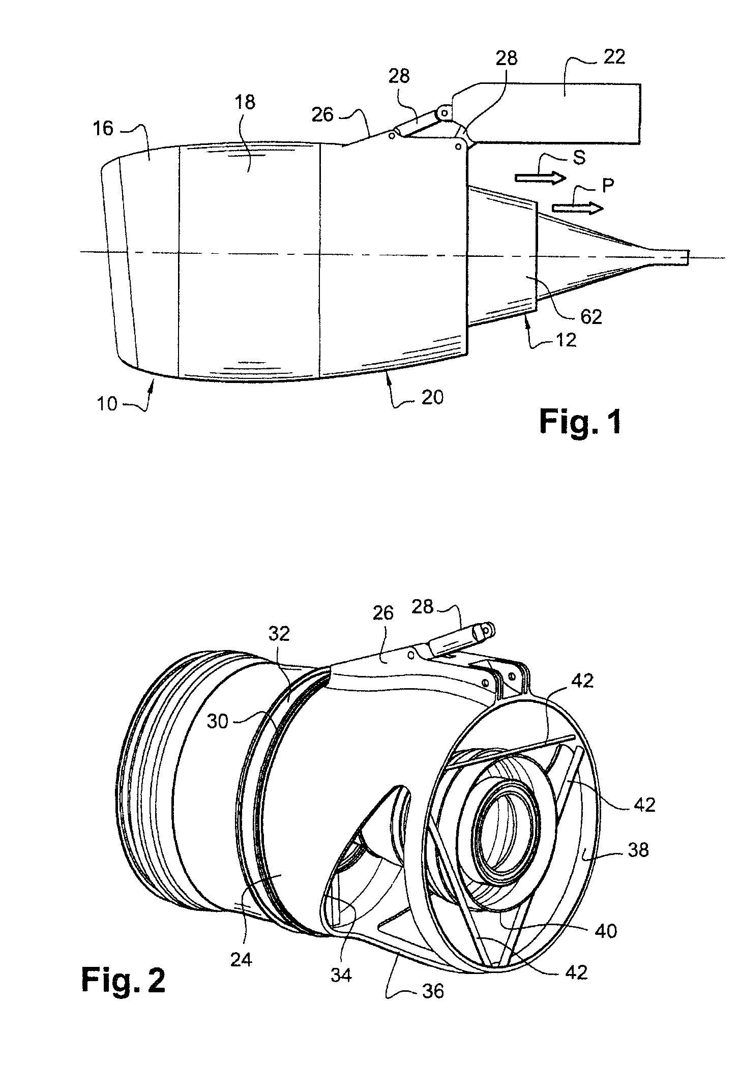
[0024]The propulsion assembly depicted schematically in FIGS. 1 and 2 essentially comprises a nacelle 10 of cylindrical shape which surrounds a turbojet 12 only the rear part of which is visible in FIG. 1 and a fan impeller (not visible) mounted inside the nacelle 10 in front of the engine, this fan impeller being driven by the turbine of the turbojet in a way well known to those skilled in the art.

[0025]While the engine is in operation, the fan generates a bypass-air stream which flows through the nacelle 10 toward the rear around the turbojet 12 and which produces 80% of the thrust provided by the engine. Some of the air entering the engine 10 is fed into the turbojet inlet compressor and is then mixed with fuel in the combustion chamber. The combustion gases leaving the combustion chamber pass through the turbine and are then ejected into an exhaust case and leave the turbojet as indicated by the arrow P in FIG. 1, in which the nearby arrow S denotes the outlet of the bypass air....


PUM


Abstract

A propulsion system for an airplane having an integrated pylon includes a bypass turbojet and a nacelle. The nacelle has a downstream cylindrical part which is rigid and is attached at its upstream end to an intermediate case of the engine. This downstream cylindrical part also includes a longitudinal beam for attaching rods to secure the engine to the airplane.

Description

BACKGROUND OF THE INVENTION AND DESCRIPTION OF THE PRIOR ART[0001]The invention relates to a bypass turbojet engine airplane propulsion system comprising a nacelle borne by an intermediate case of the engine and which delimits a space for the flow of bypass air around the turbojet, this bypass air being intended to provide more than 80% of the thrust.[0002]The engine is generally secured under a wing or to part of the fuselage or of the empennage of the airplane, by means of a pylon which is a part that is very robust and very heavy and is attached to the engine at several points through suspensions through which the loads transmitted between the engine and the airplane pass.[0003]The fact that the engine is attached using a pylon and suspensions also means that the thrust is reacted along a line that is offset from the axis of the engine, leading to overall flexing in the engine case line. The pylon is also attached to the engine by elements which cross and partially obstruct the s...

Claims


Application Information

Patent Timeline
Patent Type & Authority Patents(United States)
IPC IPC(8): B64D27/00B64D27/26B64D29/06
CPCB64D27/26B64D2027/264F01D25/28F02C7/20Y02T50/40Y02T50/60
Inventor GUIBERT, THIBAUD JEAN-BAPTISTELEFORT, GUILLAUMETESNIERE, MARC PATRICK
Owner SN DETUDE & DE CONSTR DE MOTEURS DAVIATION S N E C M A
Why Eureka
Try Eureka