Light emitting device package
a technology of light-emitting devices and light-emitting devices, which is applied in the direction of semiconductor/solid-state device manufacturing, semiconductor devices, electrical devices, etc., can solve the problems of increased manufacturing cost, difficulty in increasing light extraction efficiency, and waste of effort and assembly costs, so as to improve light extraction efficiency and heat dissipation performance, the effect of simplifying the structur
- Summary
- Abstract
- Description
- Claims
- Application Information
AI Technical Summary
Benefits of technology
Problems solved by technology
Method used
Image
Examples
first embodiment
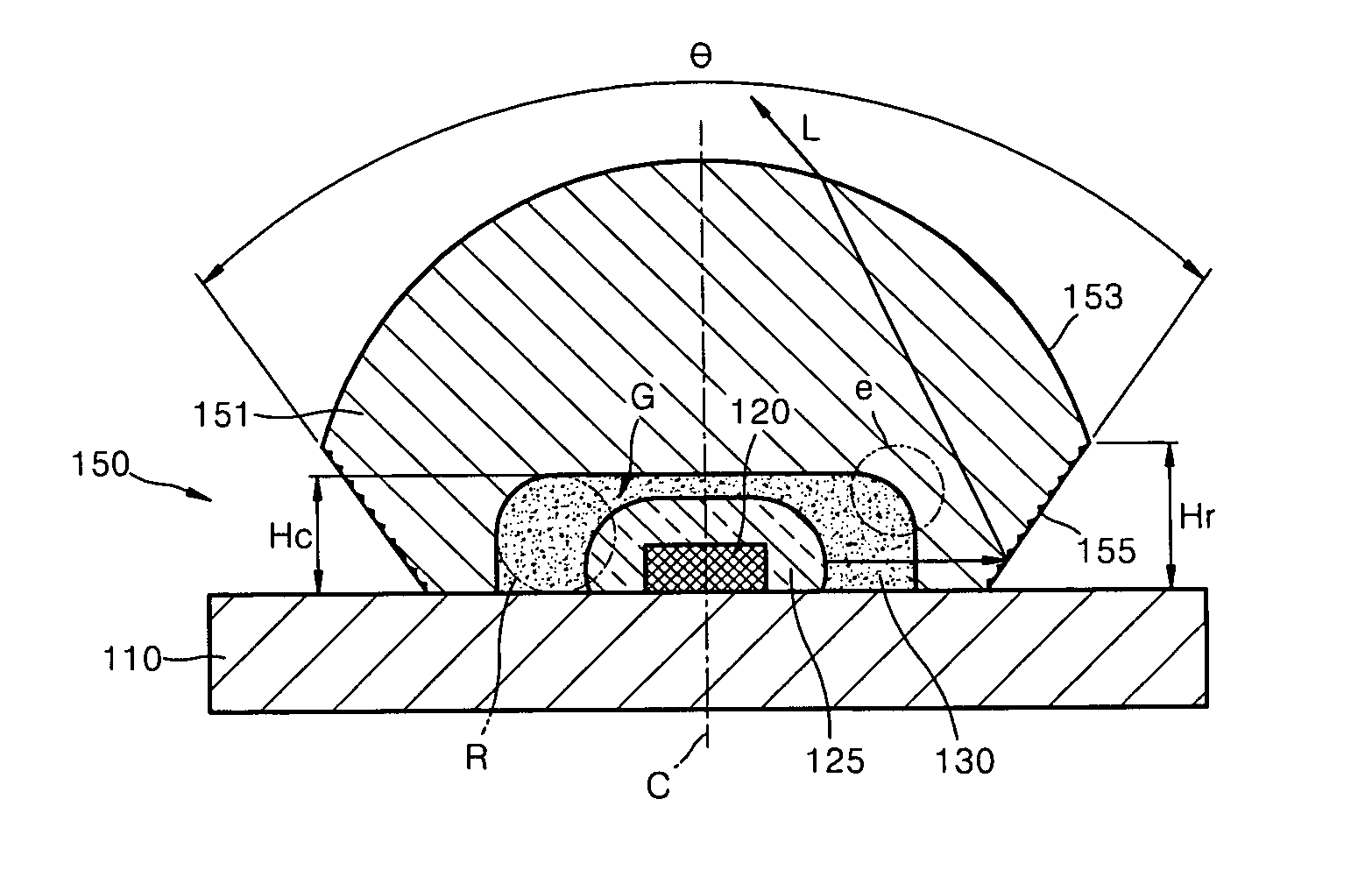
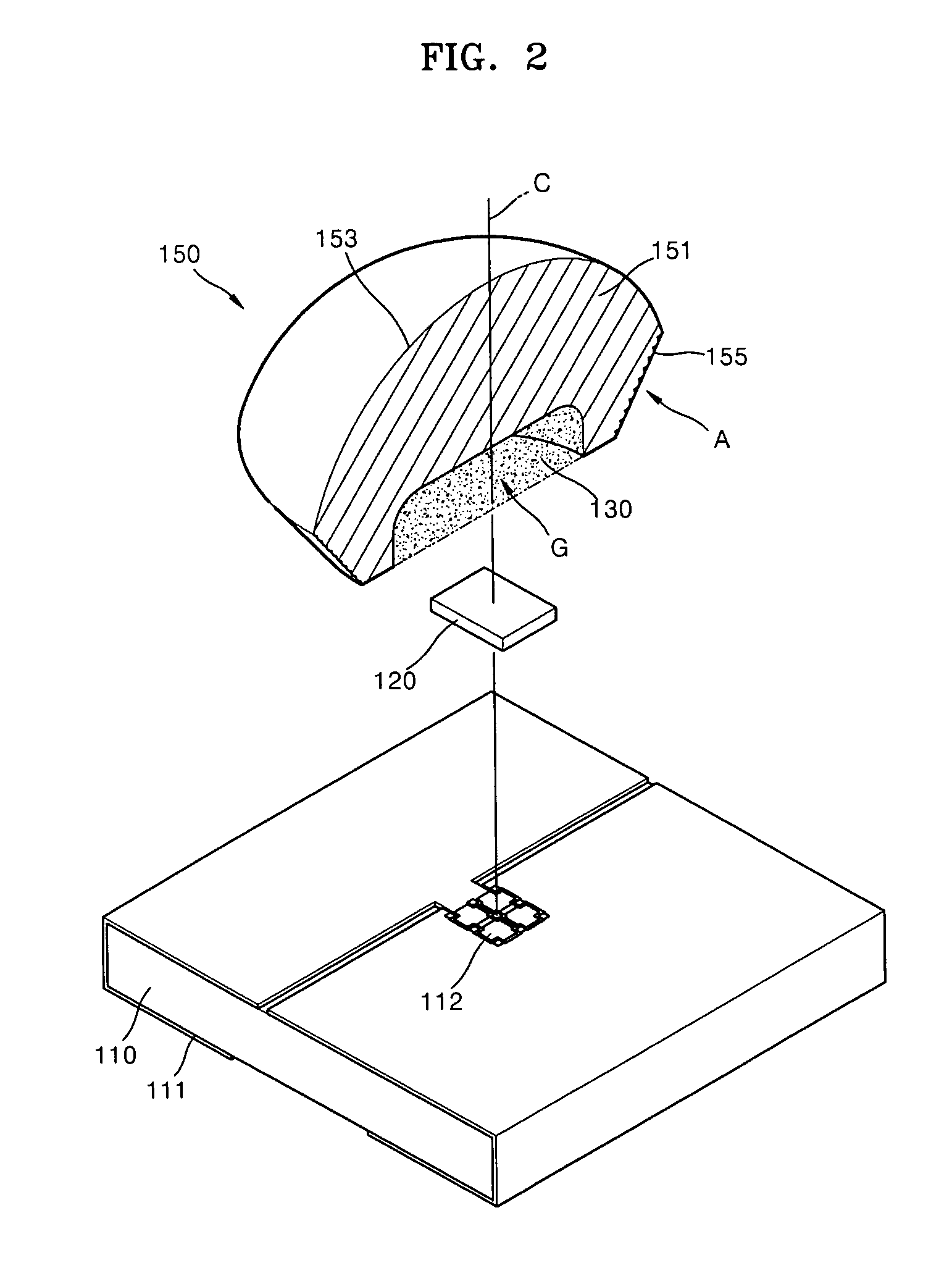
[0031]A light emitting device package of the present invention will now be described more fully with reference to the accompanying drawings, in which preferred exemplary embodiments of the invention are shown. FIG. 2 is an exploded perspective view of the light emitting device package according to the present invention. Referring to this drawing, the light emitting device package includes a base substrate 110 on which a wiring pattern 111 is formed, a light emitting device 120 mounted on the base substrate 110 to emit light when supplied with power via the wiring pattern 111, a molded lens 150 stably seated on the base substrate 110 to cover the light emitting device 120 and extract light emitted from the light emitting device 120 with high efficiency, and a sealing resin 130 injected into an inner space G between the molded lens 150 and the base substrate 110 to bond the molded lens 150 to the base substrate 110. The light emitting device 120 includes an electrode pattern (not show...
second embodiment
[0042]FIG. 5 is a perspective view of a light emitting device package according to the present invention. Referring to this, a light emitting device 220 is packaged between a base substrate 210 and a molded lens 250. A sealing resin 230 is injected into an inner space G which contains the light emitting device 220, to bond the base substrate 210 to the molded lens 250. A transparent body 251 of the molded lens 250 has a transmission surface 253 through which light is emitted from the light emitting device 220, and a reflective surface 255 inclined inward from the transmission surface 253.
[0043]In this embodiment, unlike the first embodiment, a separate sub-mount 240 is interposed between the light emitting device 220 and the base substrate 210. The sub-mount 240 physically and electrically bonds the light emitting device 220 to the base substrate 210. To this end, the sub-mount 240 may first be flip-chip bonded to the base substrate 210 below and then flip-chip bonded to the light e...
PUM
 Abstract
Description
Claims
Application Information
 - R&D
- Intellectual Property
- Life Sciences
- Materials
- Tech Scout
- Unparalleled Data Quality
- Higher Quality Content
- 60% Fewer Hallucinations
Browse by: Latest US Patents, China's latest patents, Technical Efficacy Thesaurus, Application Domain, Technology Topic, Popular Technical Reports.
© 2025 PatSnap. All rights reserved.Legal|Privacy policy|Modern Slavery Act Transparency Statement|Sitemap|About US| Contact US: help@patsnap.com


