Rotor orientation detection in brushless DC motors

a brushless dc motor and rotor orientation technology, applied in the direction of motor/generator/converter stopper, electronic commutator, dynamo-electric converter control, etc., can solve the problem of increasing the possibility of error, not being able to monitor an induced back emf, and being more susceptible to nois

Active Publication Date: 2011-05-17
MELEXIS TECH NV
View PDF10 Cites 11 Cited by
  • Summary
  • Abstract
  • Description
  • Claims
  • Application Information

AI Technical Summary

Benefits of technology

[0006]It is therefore an object of the present invention to provide a method of determining...

Problems solved by technology

Monitoring an induced back EMF is not possible when the rotor is stationary e.g. at start up and may also be difficult shortly after start up when the rotor speed is low.
Measuring in this manner using a minimum of two stator phases at every step increases the possibilities for error due to a smaller saturation effect and greater noise.
This is a particular problem when the rotor is positioned c...

Method used


Image

  • Rotor orientation detection in brushless DC motors
  • Rotor orientation detection in brushless DC motors
  • Rotor orientation detection in brushless DC motors

Examples


Embodiment Construction

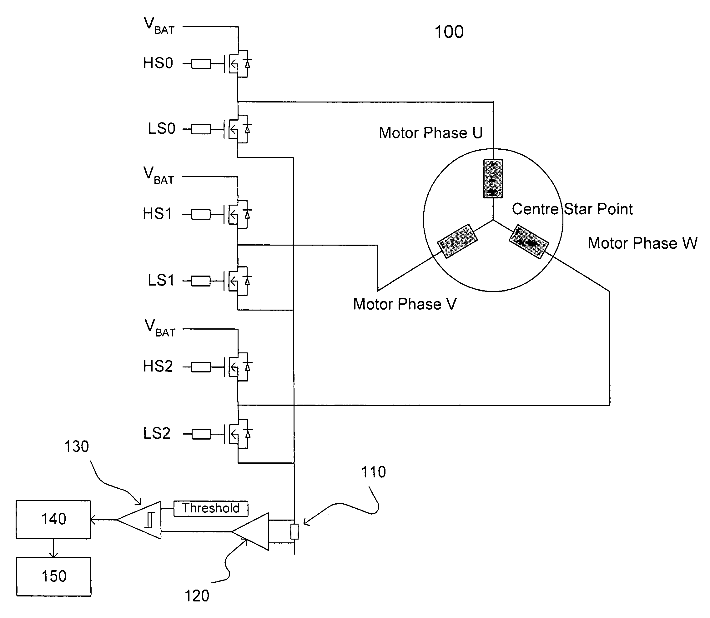
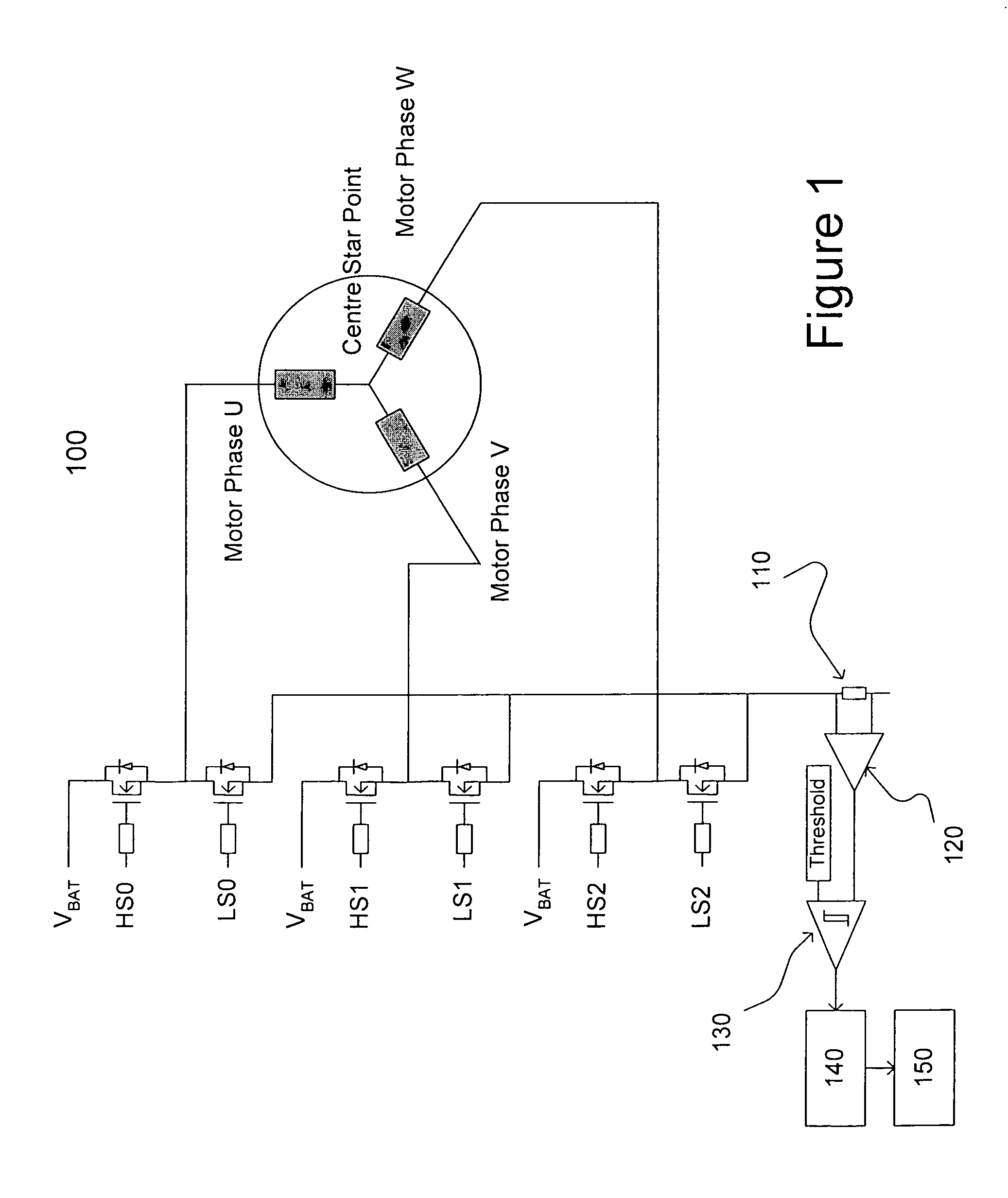
[0020]Referring now to FIG. 1, a brushless DC motor 100 comprises three stator phases U, V and W. The stator phases U, V and W are connected together at a central star point and are connected separately to driving electronics at a phase pin: stator phase U being driven via drivers HS0 and LS0; stator phase V being driven via drivers HS1 and LS1; and stator phase W being driven via drivers HS2 and LS2. In the present example, when the respective HS drivers are activated, a current flows in the respective stator phase in the direction from the star point to the phase pin (defined as a negative direction for the purposes of the present description). Conversely, when the respective LS drivers are activated, a current flows in the respective stator phase in the direction from the phase pin to the star point (defined as a positive direction for the purposes of the present description).

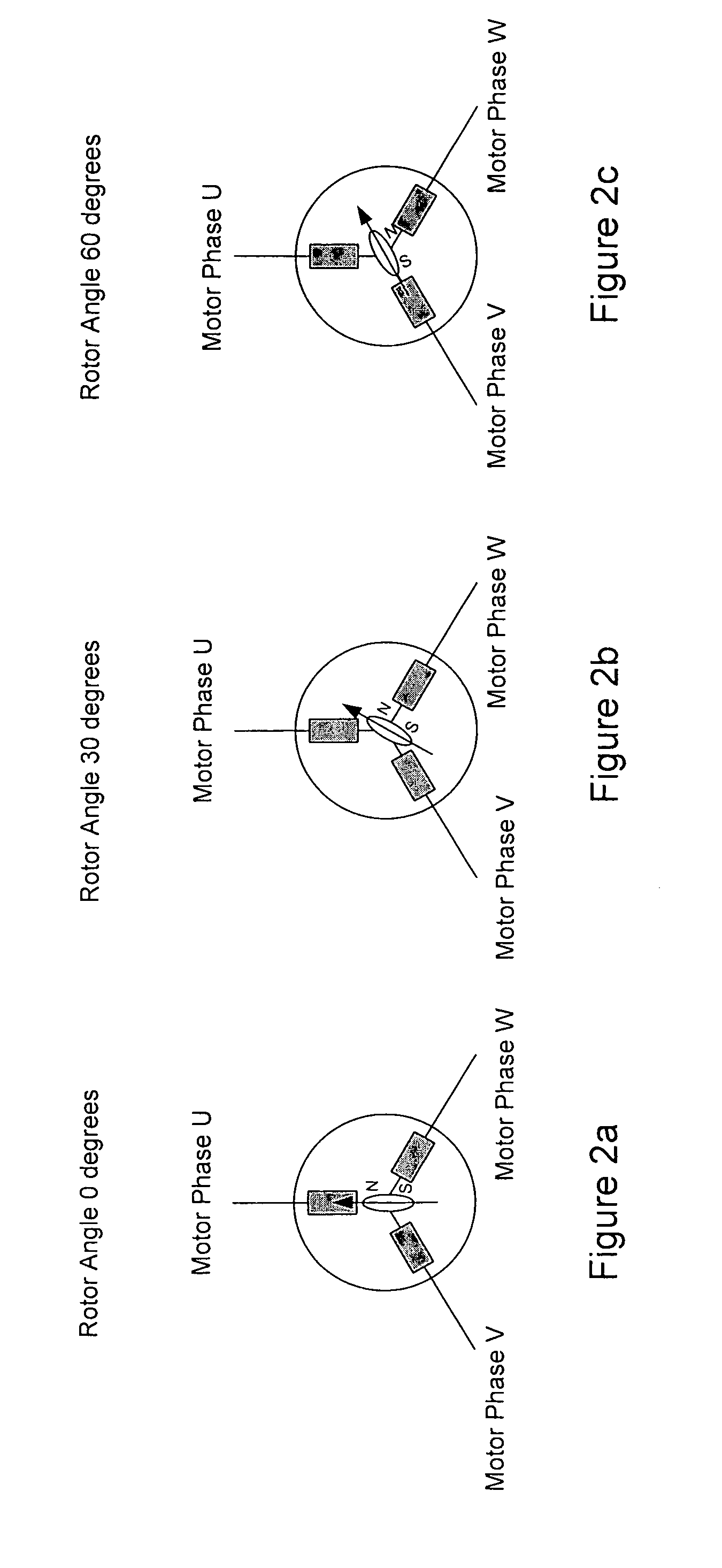
[0021]In order to determine the orientation of the rotor, a sequence of current pulses may be applied to ...


PUM


Abstract

In order to determine the orientation of the rotor of a brushless DC motor 100, a sequence of current pulses may be applied to the stator phases U, V, W by the respective drivers HS0, LS0, HS1, LS1, HS2, LS2. The current generated in the stator phases U, V, W in turn generates a current in a shunt resistor 110. The current in this shunt resistor 110 is monitored by use of a current voltage converter 120 and a comparator 130 to determine when it exceeds a predetermined threshold. The rise time until the threshold current is exceeded is recorded in capture unit 140. A processor unit 150 then calculates a scalar parameter SU, SV, SW for each respective stator phase U, V, W from the recorded rise times associated with each pulse. The orientation of the magnetic axis of the rotor can then be determined by consideration of the scalar parameters SU, SV, SW of each stator phase U, V, W, as the respective rise times of each pulse are determined by the inductive properties of the respective stator phases U, V, W, which in turn are dependent upon the orientation of the rotor.

Description

CROSS-REFERENCES TO RELATED APPLICATIONS[0001]This application claims priority to United Kingdom Application No. 0707672.2, filed Apr. 20, 2007, the disclosure of which is herein incorporated by reference.BACKGROUND OF THE INVENTION[0002]The present invention relates to the determination of rotor orientation in brushless DC motors and in particular to the determination of rotor orientation when the rotor is stationary or rotating relatively slowly.[0003]In order to drive a brushless DC motor, it is necessary to detect the orientation of the magnetic axis of the permanently magnetic rotor such that the appropriate driving current may be fed to each stator phase. A stator phase is built up from one or more coils, depending on motor geometry. This can be achieved by the provision of dedicated sensor means, such as a Hall effect sensor. Alternatively, it is possible to determine the rotor orientation without an additional dedicated sensor.[0004]This can be achieved by monitoring the pha...

Claims


Application Information

Patent Timeline
IPC IPC(8): H02P6/00
CPCH02P6/185H02P6/142H02P6/15
Inventor PAINTZ, CHRISTIANFREITAG, THOMASKLOSE, DETLEF
Owner MELEXIS TECH NV
Why Eureka
Try Eureka