
Illumination systems

a technology of polarization components and polarization beams, applied in the field of polarization systems, can solve the problems of large beams, color and polarization components are generally not divided and recombined in the dichroic approach does not generally provide for the splitting and recombining of colors and polarization components back into a single combined beam, so as to reduce the loss of combining and polarizing

Inactive Publication Date: 2011-05-17
REAID INC
View PDF23 Cites 2 Cited by
  • Summary
  • Abstract
  • Description
  • Claims
  • Application Information

AI Technical Summary

Benefits of technology

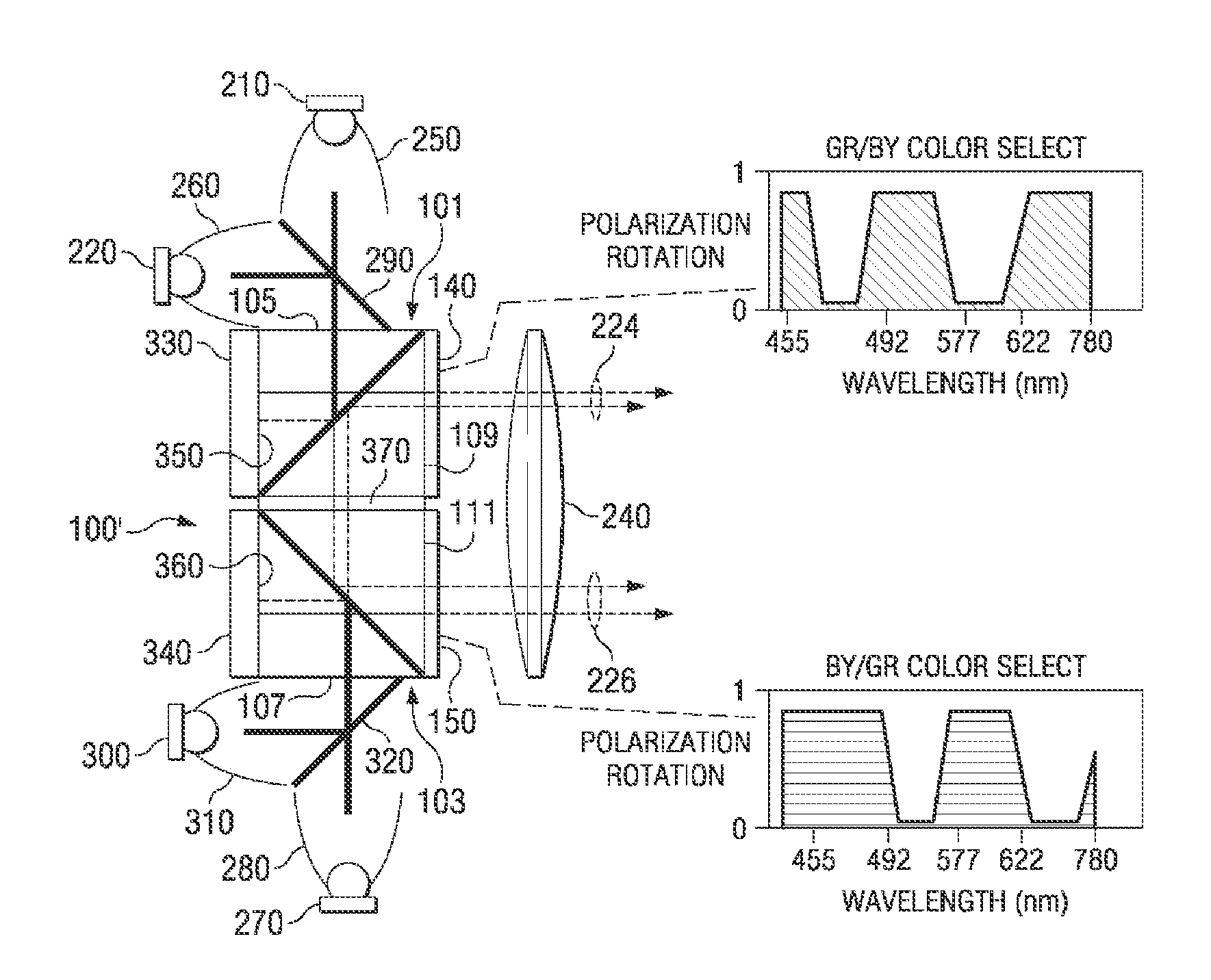
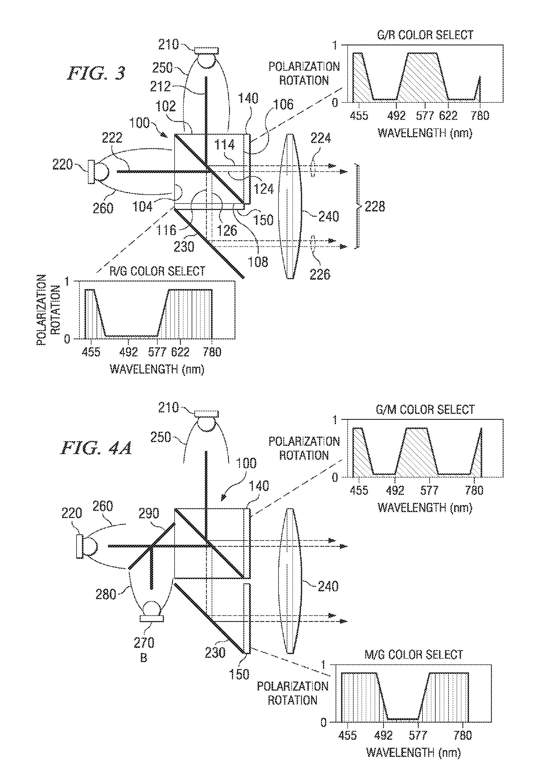
Disclosed in this application is a technique whereby the light spectra from multiple LEDs of varying colors can be combined and polarized with minimal components, while substantially reducing the losses during combining and polarizing. The described techniques use polarizing beam splitters (PBSs) with retarder stack filters to combine color and convert polarization for mixed component light beams in one step, and to ultimately align the polarizations of the several colored light beams.
Further disclosed is a method and apparatus using a combination of polarization sensitive beam splitters (PBSs) in conjunction with polarization color selective filters or retarder stack filters to accomplish the tasks of color combination and polarization conversion in an integrated illumination system consisting of separate different colored sources. Conceptually, the method physically separates colored beams emanating from two or more differently colored sources into orthogonal polarization states with a single PBS. The orthogonal polarized beams of the different colors are then manipulated with retarder stack filters to form uniformly polarized beams that are combined optically. The complementary operations of combining colors and polarizations allow compact and efficient systems to be realized. Efficient optical systems exhibit both low loss and minimal optical extent in the final illuminating beam. The specific embodiments include collimating optics required for practical systems.

Problems solved by technology

The dichroic approach does not generally provide for the splitting and recombining of colors and polarization components back into a single combined beam.
In the all-dichroic approach, a larger beam of aligned and commonly polarized light is typically formed using two steps; larger beams are of course undesirable from a system-design standpoint.

Method used


Image

  • Illumination systems
  • Illumination systems
  • Illumination systems

Examples


Embodiment Construction

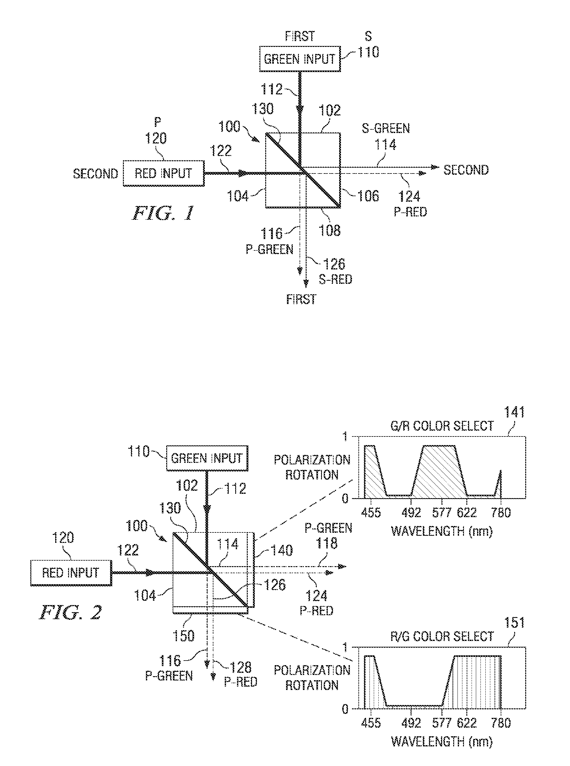
FIG. 1 illustrates a polarization-separating unit 100 embodied as a single PBS element 100. Also shown are a first light source 110 and a second light source 120. The PBS 100 accepts light represented by line 112 from the first light source 110 and light represented by line 122 from the second light source 120. In the present embodiment, the light 112 from the first light source 110 is green and the light 122 from the second light source 120 is red. However, these colors are used only as examples, and are not intended to be limiting. That is, the light sources 110, 120 can be selected that emit any color of light. The PBS 100 acts to separate each beam 112, 122 independently into orthogonal polarized states. In the PBS 100, that component of light having its electric field substantially orthogonal to the plane of incidence (conventionally termed s-polarization) becomes reflected by the surface 130, while that component of the light having its electric field within the plane of incid...


PUM


Abstract

Described are illumination systems whereby light spectra from multiple LEDs of various colors can be combined and polarized with minimal components, while substantially reducing the losses for the combining and polarizing. The described systems and methods use polarizing beam splitters (PBSs) with retarder stack filters to combine color and split polarization for mixed light beams in one step, and to ultimately align the polarizations of the several colored light beams.

Description

TECHNICAL FIELDDisclosed embodiments relate generally to illumination systems incorporating different colored light sources, such as laser light sources or light emitting diodes (LEDs). Generally disclosed applications herein relate to polarization-sensitive projection of images from micro-display optical modulators. Specific systems include head-mounted, head-up, rear-projection, and front-projection displays.BACKGROUNDDue to their relatively low power consumption and long lives, LEDs are desirable light sources. Laser light sources are at times desirable because of their long lives, high intensity, and superior collimation. LEDs and laser light sources are narrow-band light sources, or in other words, provide colored light. While these light sources provide unpolarized light, there are many applications for which polarized light is desired. LCDs, for example, operate on polarized light, and so to use one of these light sources to illuminate an LCD-based display, it would be necess...

Claims


Application Information

Patent Timeline
IPC IPC(8): G02B5/30G02B27/28H01L33/00H01L33/58H01L33/60
CPCG02B27/102G02B27/14G02B27/141G02B27/144G02B27/285G02B27/148G02B27/149G02B27/283G02B27/145Y10S359/90Y10S362/80
Inventor ROBINSON, MICHAEL G.
Owner REAID INC
Learn More